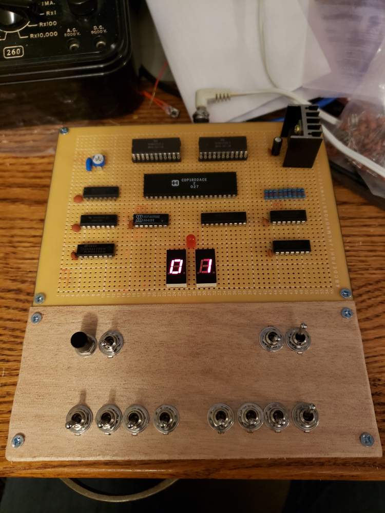
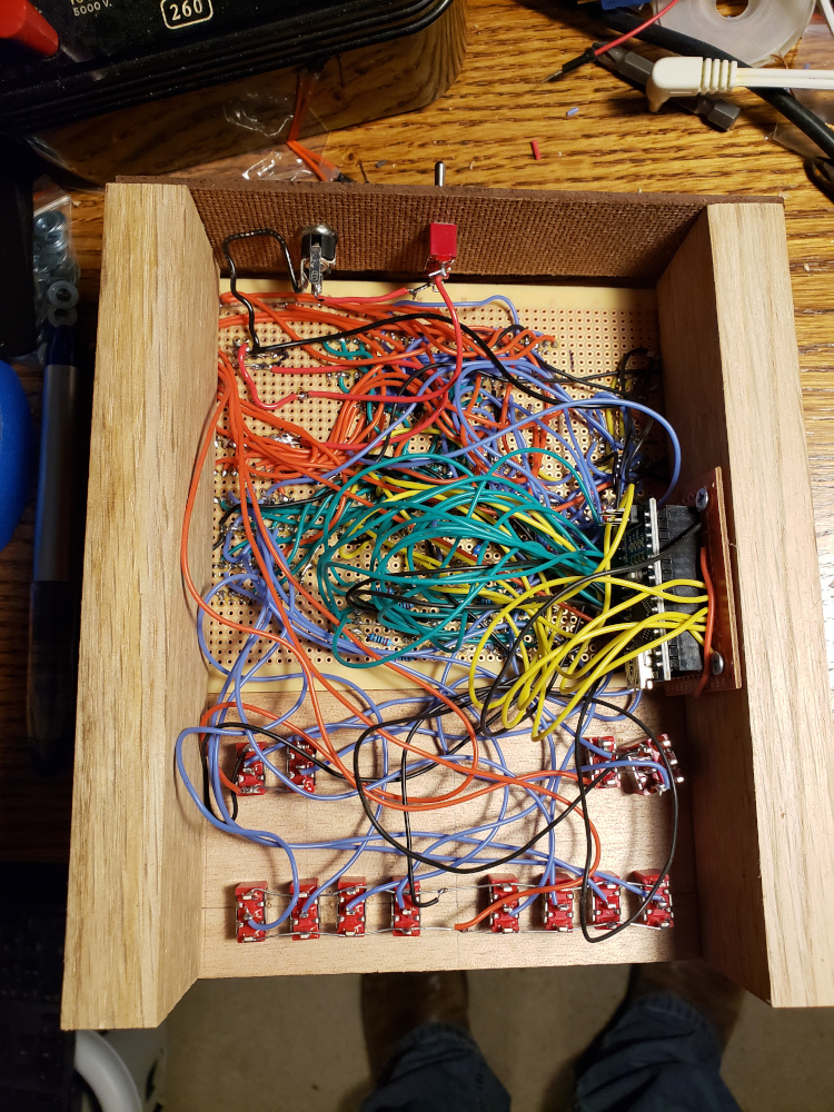
  1
  2
  3
  4
  5
  6
  7
  8
  9
 10
 11
 12
 13
 14
 15
 16
 17
 18
 19
 20
 21
 22
 23
 24
 25
 26
 27
 28
 29
 30
 31
 32
 33
 34
 35
 36
 37
 38
 39
 40
 41
 42
 43
 44
 45
 46
 47
 48
 49
 50
 51
 52
 53
 54
 55
 56
 57
 58
 59
 60
 61
 62
 63
 64
 65
 66
 67
 68
 69
 70
 71
 72
 73
 74
 75
 76
 77
 78
 79
 80
 81
 82
 83
 84
 85
 86
 87
 88
 89
 90
 91
 92
 93
 94
 95
 96
 97
 98
 99
100
101
102
103
104
105
106
107
108
109
110
111
112
113
114
115
116
117
118
119
120
121
122
123
124
125
126
127
128
129
130
131
132
133
134
135
136
137
138
139
140
141
142
143
144
145
146
147
148
149
150
151
152
153
154
155
156
157
158
159
160
161
162
163
164
|
// Seven Segment Display Connections
#define A_SEGMENT 2
#define B_SEGMENT 3
#define C_SEGMENT 4
#define D_SEGMENT 5
#define E_SEGMENT 6
#define F_SEGMENT 7
#define G_SEGMENT 8

#define DIGIT_1_GND 9
#define DIGIT_2_GND 10

// Data Bus Pins
#define bus0 11
#define bus1 12
#define bus2 13
#define bus3 A0
#define bus4 A1
#define bus5 A2
#define bus6 A3
#define bus7 A4

int COUNT = 0;

void setup() {

  TIMSK2 = (TIMSK2 & B11111110) | 0x01;
  TCCR2B = (TCCR2B & B11111000) | 0x05;

  pinMode(A_SEGMENT, OUTPUT);
  pinMode(B_SEGMENT, OUTPUT);
  pinMode(C_SEGMENT, OUTPUT);
  pinMode(D_SEGMENT, OUTPUT);
  pinMode(E_SEGMENT, OUTPUT);
  pinMode(F_SEGMENT, OUTPUT);
  pinMode(G_SEGMENT, OUTPUT);

  pinMode(DIGIT_1_GND, OUTPUT);
  pinMode(DIGIT_2_GND, OUTPUT);

  pinMode(bus0, INPUT);
  pinMode(bus1, INPUT);
  pinMode(bus2, INPUT);
  pinMode(bus3, INPUT);
  pinMode(bus4, INPUT);
  pinMode(bus5, INPUT);
  pinMode(bus6, INPUT);
  pinMode(bus7, INPUT);

}

void loop() {}

void read_bus() {

  byte value = 0;

  bitWrite(value, 0, digitalRead(bus0));
  bitWrite(value, 1, digitalRead(bus1));
  bitWrite(value, 2, digitalRead(bus2));
  bitWrite(value, 3, digitalRead(bus3));
  bitWrite(value, 4, digitalRead(bus4));
  bitWrite(value, 5, digitalRead(bus5));
  bitWrite(value, 6, digitalRead(bus6));
  bitWrite(value, 7, digitalRead(bus7));

  String output_string =  '0' + String(value, HEX);

  output_string = output_string.substring(output_string.length() - 2, output_string.length());

  // alternate writes to each display
  if ((COUNT & 0x01) == 0) {
    write_char(output_string.charAt(0), 2);
    write_char(output_string.charAt(1), 1);
  } else {
    write_char(output_string.charAt(1), 1);
    write_char(output_string.charAt(0), 2);
  }

  COUNT += 1;

}

ISR(TIMER2_OVF_vect) {
  // time based interrupt routine
  read_bus();
}

void write_char(char character, int digit) {

  byte char_val;

  switch (character) {
  case '0':
    char_val = 0b11111100; // 0
    break;
  case '1':
    char_val = 0b01100000; // 1
    break;
  case '2':
    char_val = 0b11011010; // 2
    break;
  case '3':
    char_val = 0b11110010; // 3
    break;
  case '4':
    char_val = 0b01100110; // 4
    break;
  case '5':
    char_val = 0b10110110; // 5
    break;
  case '6':
    char_val = 0b10111110; // 6
    break;
  case '7':
    char_val = 0b11100000; // 7
    break;
  case '8':
    char_val = 0b11111110; // 8
    break;
  case '9':
    char_val = 0b11110110; // 9
    break;
  case 'a':
    char_val = 0b11101110; // A
    break;
  case 'b':
    char_val = 0b00111110; // B
    break;
  case 'c':
    char_val = 0b10011100; // C
    break;
  case 'd':
    char_val = 0b01111010; // D
    break;
  case 'e':
    char_val = 0b10011110; // E
    break;
  case 'f':
    char_val = 0b10001110; // F
    break;
  default:
    break;
}

  digitalWrite(A_SEGMENT, (char_val & 0b10000000) >> 7 );
  digitalWrite(B_SEGMENT, (char_val & 0b01000000) >> 6 );
  digitalWrite(C_SEGMENT, (char_val & 0b00100000) >> 5 );
  digitalWrite(D_SEGMENT, (char_val & 0b00010000) >> 4 );
  digitalWrite(E_SEGMENT, (char_val & 0b00001000) >> 3 );
  digitalWrite(F_SEGMENT, (char_val & 0b00000100) >> 2 );
  digitalWrite(G_SEGMENT, (char_val & 0b00000010) >> 1 );


  if ( digit == 1 ) {
    digitalWrite(DIGIT_1_GND, LOW);
    digitalWrite(DIGIT_2_GND, HIGH);
  } else if ( digit == 2 ) {
    digitalWrite(DIGIT_1_GND, HIGH);
    digitalWrite(DIGIT_2_GND, LOW);
  }
  delay(2);

}
|

