Wow. Its been over a year since I last posted anything.
Over the past two years, I’ve been working as the project manager for a large software/infrastructure implementation, so that has taken up most of my time. That project started a month or two before COVID hit and we basically powered through the entire pandemic with our primary team on-site for all but a few weeks when our state issued a shelter in place order.
We finally launched on November first of 2021, so now I am mainly supporting the organization while everyone gets up to speed. That means that I’ve started to have some free time again on nights and weekends. Yay!
Since the launch, I’ve converted this site to a new backend and revisited the 6502 computer that I started about a year ago.
In a previous post, I made a version of Ben Eater’s 6502 breadboard computer. I changed around the memory map and added some dual port video ram and an MC6847 to output composite video.
I then got caught up in other things and left it sitting on the desk for a while.
The breadboard connections were always a little flakey, so I started rebuilding it on another breadboard and then just decided to solder it up on some strip board.
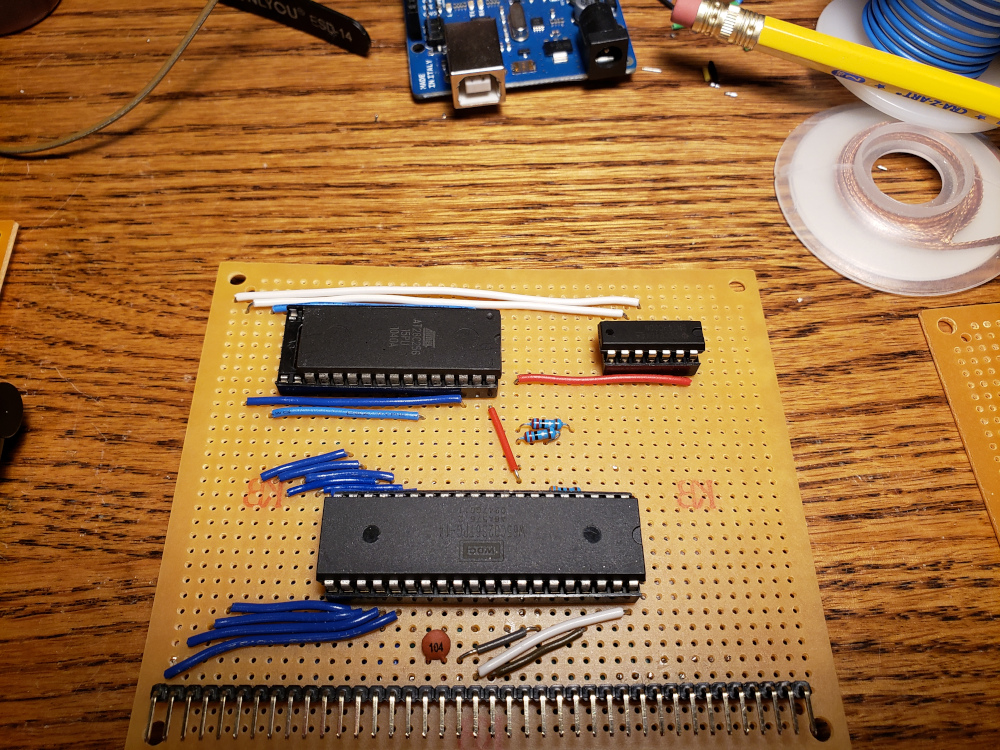
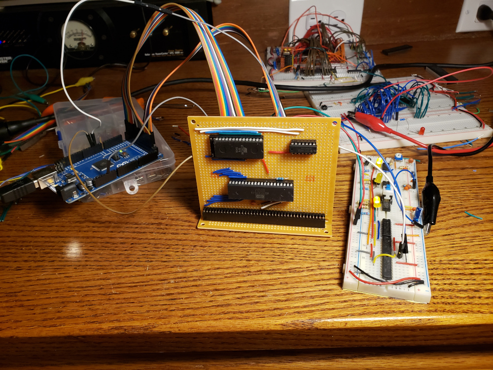
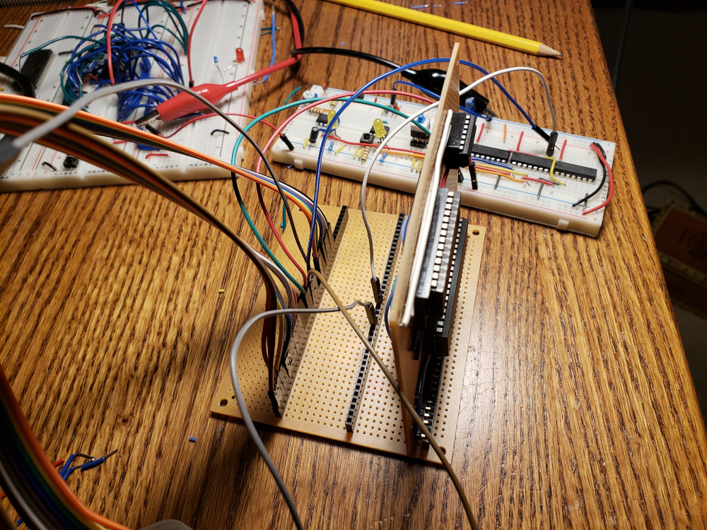
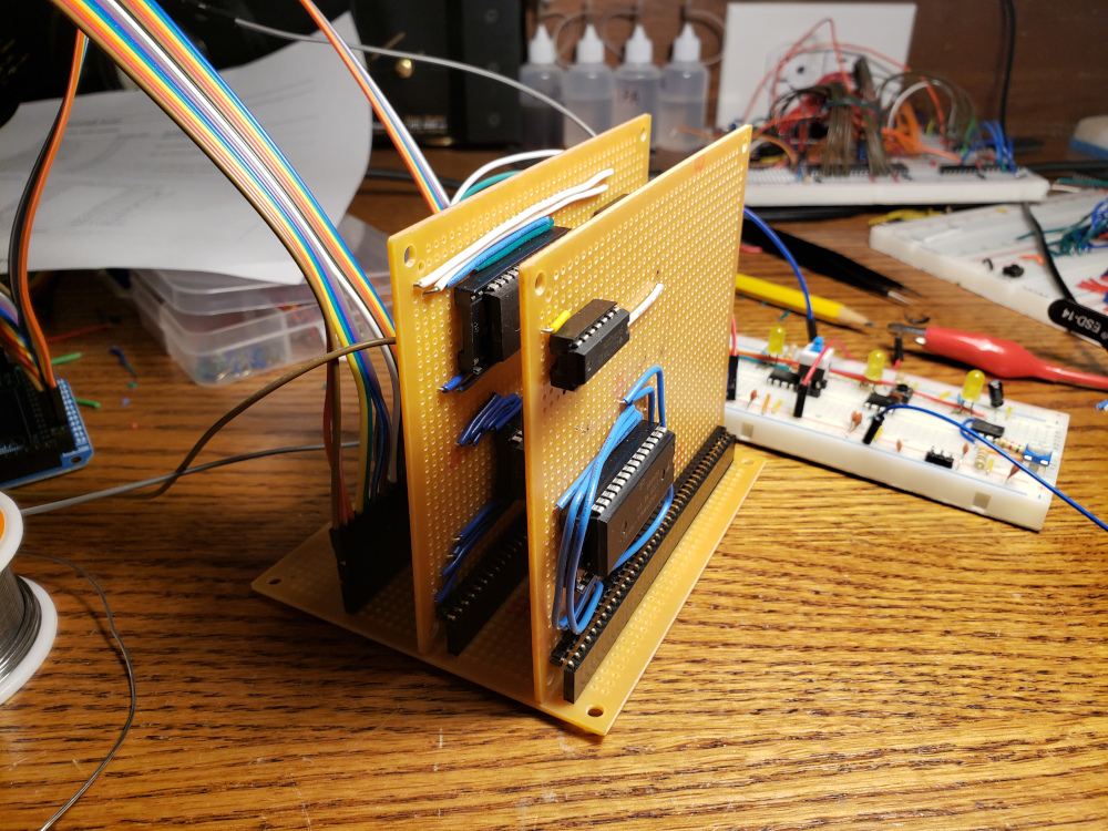
I took inspiration from the RC2014 and how it used pin headers and sockets for cards and a backplane, so I started out building the CPU/ROM board and a backplane.
Below is the pin layout for the backplane. I’m not currently using pins 31 through 40, so I’ve got some room for expansion.
 1
 2
 3
 4
 5
 6
 7
 8
 9
10
11
12
13
14
15
16
17
18
19
20
21
22
23
24
25
26
27
28
29
30
31
32
33
34
35
36
37
38
39
40
|
A15
A14
A13
A12
A11
A10
A09
A08
A07
A06
A05
A04
A03
A02
A01
GND
+5V
R/W
RST
CLK
IRQ
NMIB
D0
D1
D2
D3
D4
D5
D6
D7
|

I used the slow clock breadboard module and the arduino mega to monitor the signals on the backplane to verify that things were working correctly.


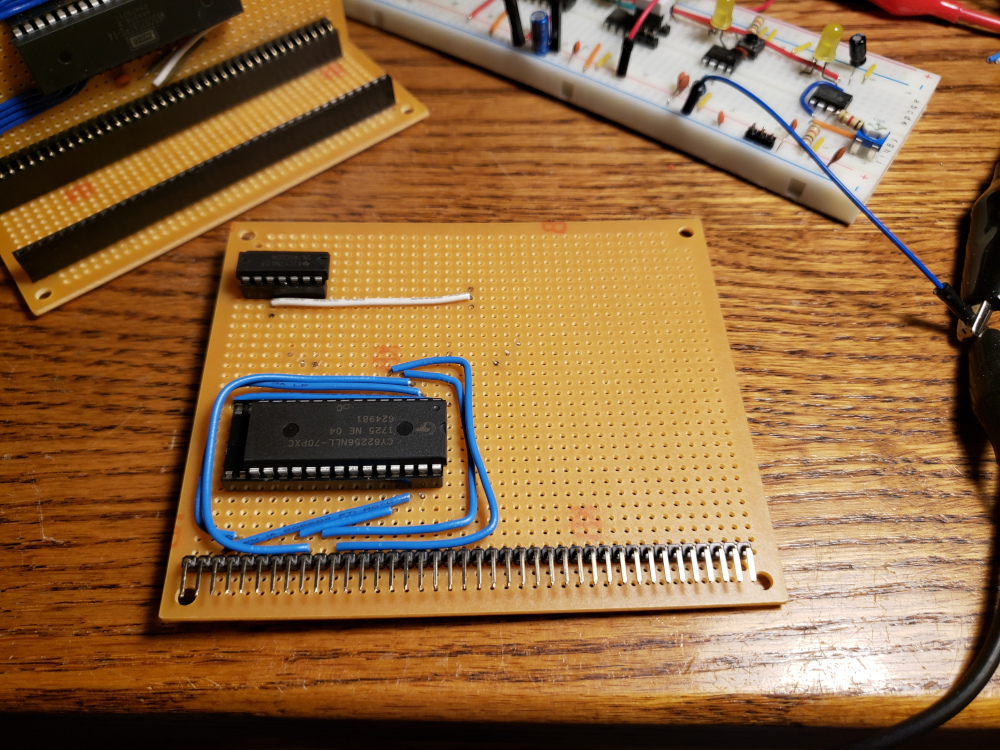
With the CPU and ROM working, I built a RAM board.


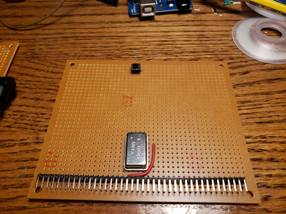
The RAM tested good with the slow clock, so the next step is to give it a real clock. I used a 1MHz can oscillator and added a reset switch to another board.

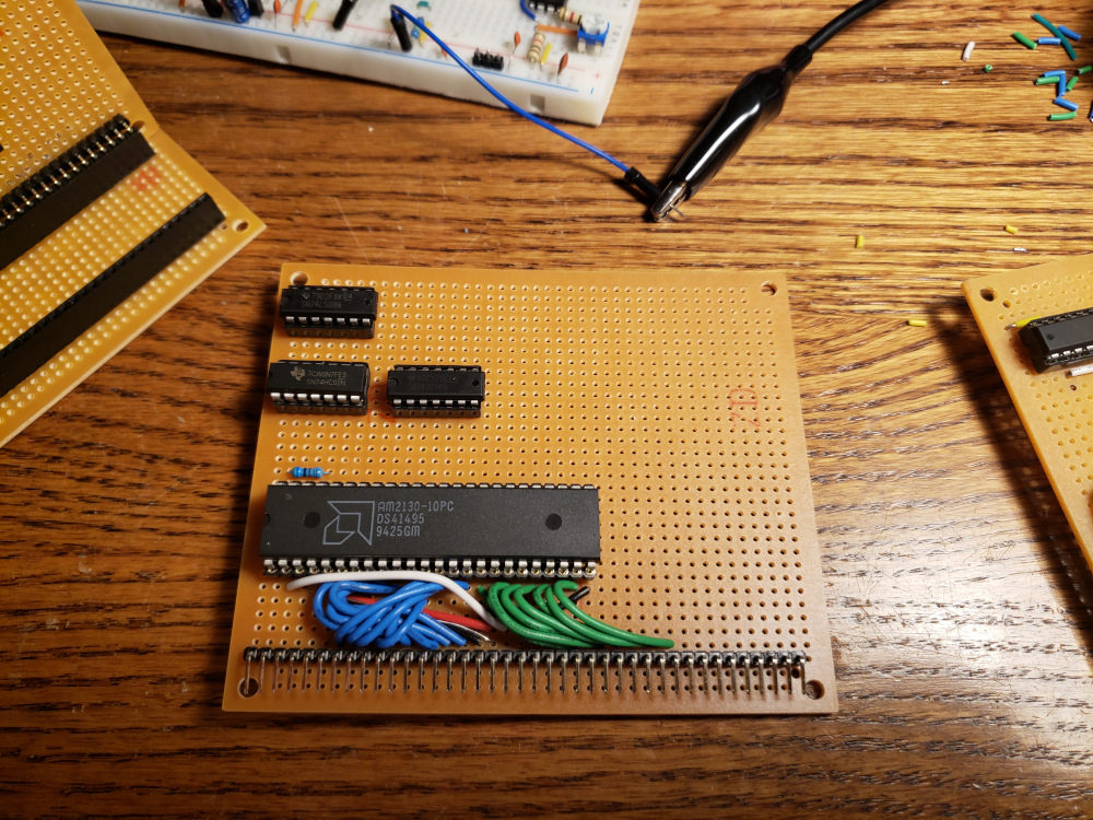
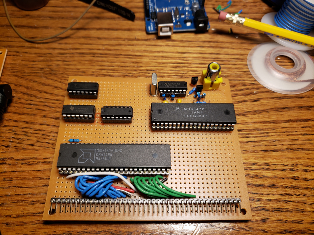
Next step is video. I started a new board with some dual port RAM to use as video memory.

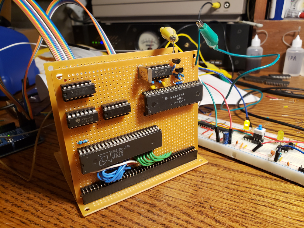
Next, I added the MC6847 and a clock circuit to drive it. I hooked it up temporarily with some alligator clips to verify that video is working.

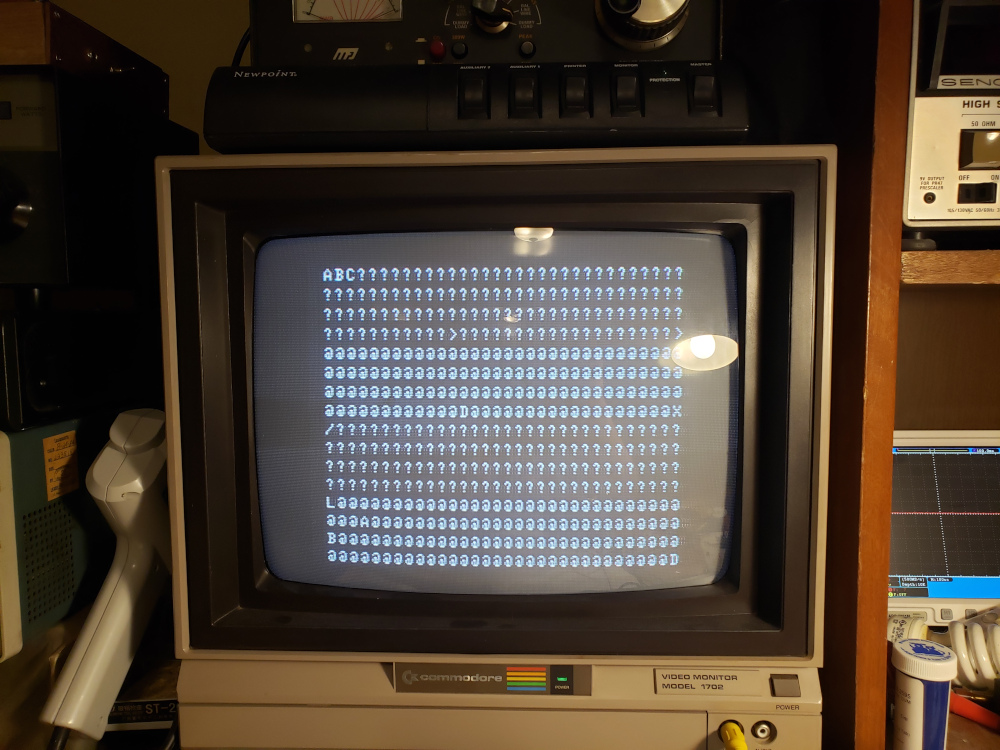
I wrote ABC to the VRAM and the MC6847 displayed it along with the rest of the initialized garbage.

With that working, I added a composite socket to the final board.

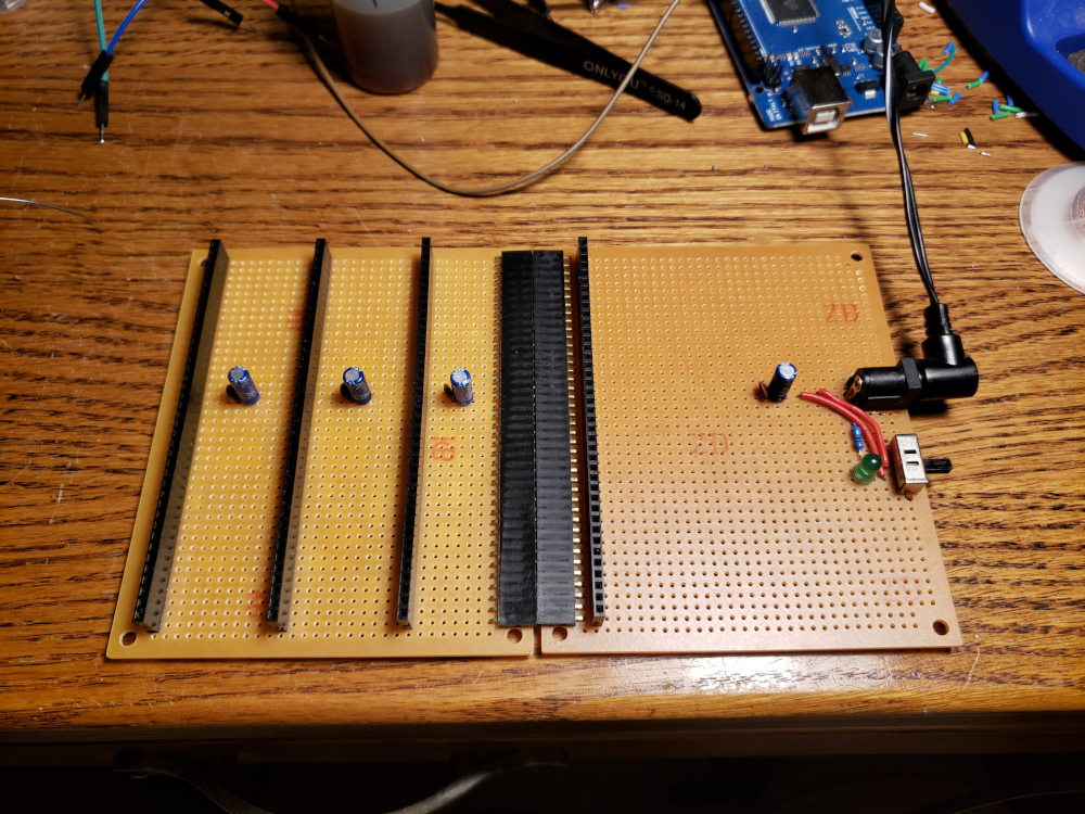
I’ve now exceeded the capacity of my original backplane, so I extended it and added a power input with a switch and LED.


Next, I wanted a keyboard input. To do that, I built a board with a WC65C22 Versatile Interface Adapter or VIA.
I wired it up to a yellow LED to blink to test the board.

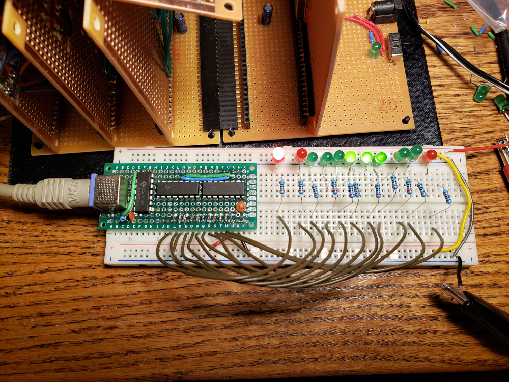
With that working, I next built a shift register board to read in the PS/2 keyboard data. The circuit is pretty much the same that Ben used in his video. The schematic I referenced is here.

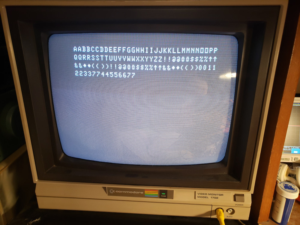
That seemed to work, so I put it all together and tested, but I was getting double characters every time I pressed a key.

I ended up having to reduce the resistor value in the RC circuit on the shift register board from 33k to 22k to fix the double characters.

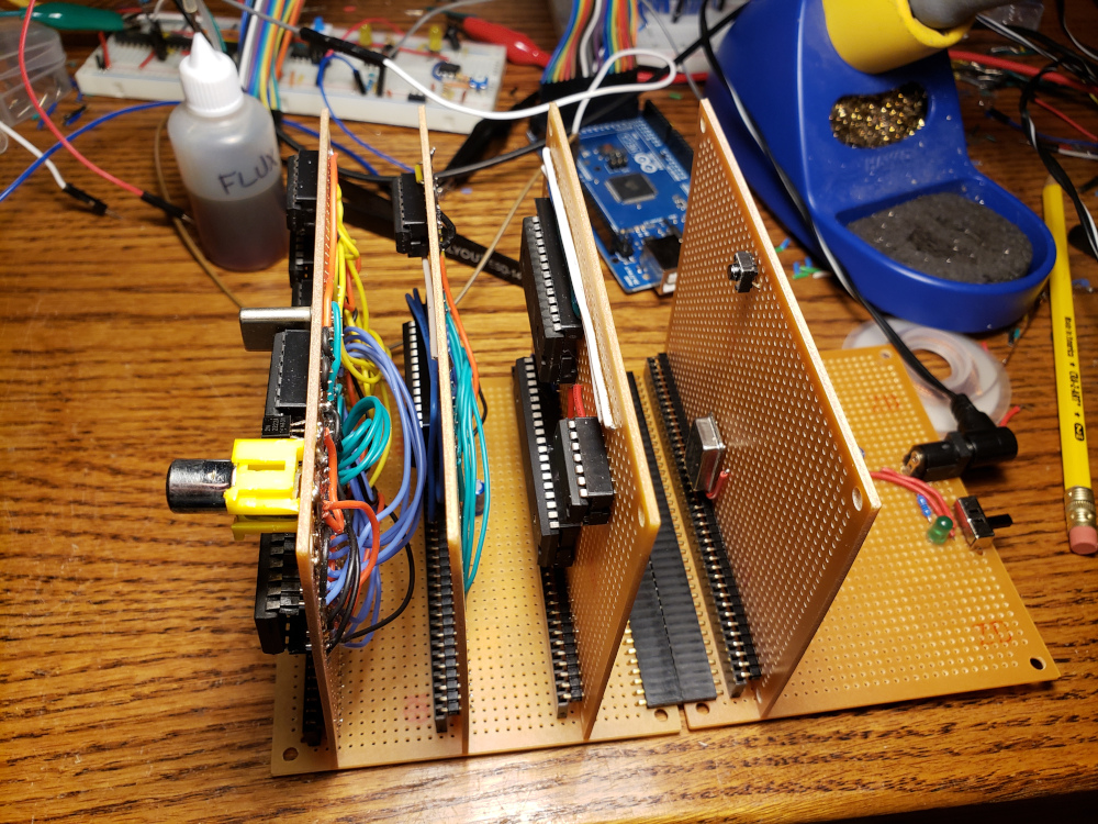
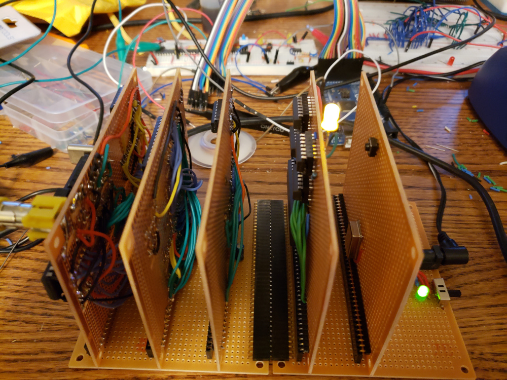
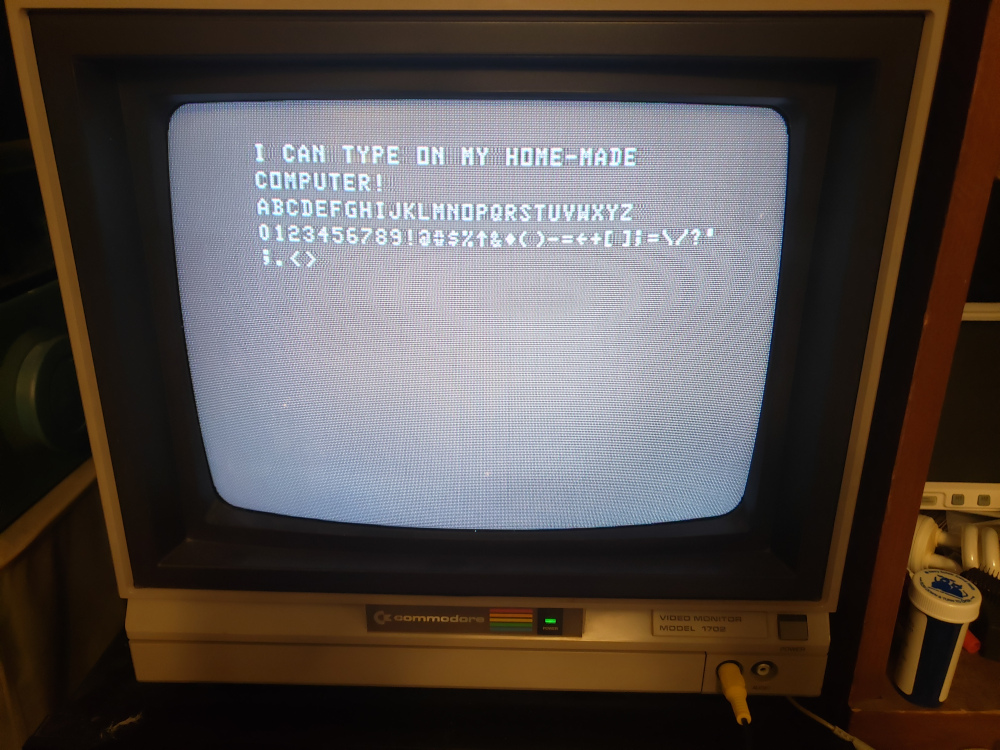
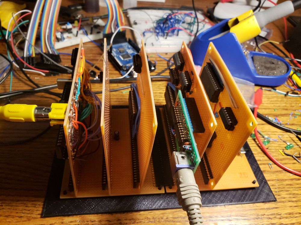
The final configuration is below. I 3D printed a little base plate with support stand-offs for the backplane to sit on.

The current code I’m using is:
  1
  2
  3
  4
  5
  6
  7
  8
  9
 10
 11
 12
 13
 14
 15
 16
 17
 18
 19
 20
 21
 22
 23
 24
 25
 26
 27
 28
 29
 30
 31
 32
 33
 34
 35
 36
 37
 38
 39
 40
 41
 42
 43
 44
 45
 46
 47
 48
 49
 50
 51
 52
 53
 54
 55
 56
 57
 58
 59
 60
 61
 62
 63
 64
 65
 66
 67
 68
 69
 70
 71
 72
 73
 74
 75
 76
 77
 78
 79
 80
 81
 82
 83
 84
 85
 86
 87
 88
 89
 90
 91
 92
 93
 94
 95
 96
 97
 98
 99
100
101
102
103
104
105
106
107
108
109
110
111
112
113
114
115
116
117
118
119
120
121
122
123
124
125
126
127
128
129
130
131
132
133
134
135
136
137
138
139
140
141
142
143
144
145
146
147
148
149
150
151
152
153
154
155
156
157
158
159
160
161
162
163
164
165
166
167
168
169
170
171
172
173
174
175
176
177
178
179
180
181
182
183
184
185
186
187
188
189
190
191
192
193
194
195
196
197
198
199
200
201
202
203
204
205
206
207
208
209
210
211
212
213
214
215
216
217
218
219
220
221
222
223
224
225
226
227
228
229
230
231
232
233
234
235
236
237
238
239
240
241
242
243
244
245
|
; pointers

KB_WPTR  = $0000
KB_RPTR  = $0001
KB_FLAGS = $0002
CURSOR   = $0003

KB_BUFFER = $0200 ; 256 byte kb buffer 0200-02ff

; constants
RELEASE = %00000001
SHIFT   = %00000010

SCREEN = $8000

VRAM_0 = $8000 ; 1st quarter of VRAM
VRAM_1 = $8100 ; 2nd quarter of VRAM
VRAM_2 = $8200 ; 3rd quarter of VRAM
VRAM_3 = $8300 ; 4th quarter of VRAM

PORTB = $8400
PORTA = $8401
DDRB  = $8402
DDRA  = $8403
PCR   = $840c
IFR   = $840d
IER   = $840e

; register select pins on 6522
; RS0 <-> A0 = $8401
; RS1 <-> A1 = $8402
; RS2 <-> A2 = $8404
; RS3 <-> A3 = $8408

  .org $c000 ; testing vram

reset:
  ldx #$ff 	; load ff in x register
  txs 		; transfer x to s to initialize stack pointers

  lda #$01
  sta PCR
  lda #$82
  sta IER
  cli

  lda #%11111111 ; set all pins on port B to output
  sta DDRB

  lda #%00000000 ; set all pins on port A to input
  sta DDRA

  lda #$00      ; initialize pointers to 0
  sta KB_WPTR
  sta KB_RPTR
  sta KB_FLAGS
  sta CURSOR

  jsr CLRSCR 	; clear the screen

loop:
  sei			; disable interrupts
  lda KB_RPTR		; compare kb read and write pointers
  cmp KB_WPTR
  cli			; enable interrupts
  bne key_pressed	; jump to key_pressed if keyboard read and write pointers differ
  jmp loop

key_pressed:
  ldx KB_RPTR		; load kb pointer
  lda KB_BUFFER, x	; read kb_buffer at read pointer
  inc KB_RPTR		; increment read pointer

  ldx CURSOR		; load cursor pointer
  sta SCREEN, x 	; store character in A register to screen at cursor offset
  inc CURSOR		; increment cursor

  jmp loop		; jump back to top of loop

;;;;;;;;;;;;;;;;;;;;;;;;;;;;;;;;;;;;;;;;;;;;;;;;;;;;
; Clear Screen
;;;;;;;;;;;;;;;;;;;;;;;;;;;;;;;;;;;;;;;;;;;;;;;;;;;;
CLRSCR:		; clear the screen
  pha
  tya
  pha

  ldy #00
  lda #$20
VRAM_INIT:
  sta VRAM_0,y
  sta VRAM_1,y
  sta VRAM_2,y
  sta VRAM_3,y
  cpy #$ff
  iny
  bne VRAM_INIT

  pla
  tay
  pla
  rts
;;;;;;;;;;;;;;;;;;;;;;;;;;;;;;;;;;;;;;;;;;;;;;;;;;;;

irq:
  pha
  txa
  pha

  lda KB_FLAGS
  and #RELEASE ; check if we're releasing a key
  beq read_key ; otherwise, read the key

  lda KB_FLAGS
  eor #RELEASE ; flip the releasing bit
  sta KB_FLAGS

  lda PORTA    ; read key value thats being released
  cmp #$12 ; left shift
  beq shift_up
  cmp #$59 ; right shift
  beq shift_up
  jmp exit

shift_up:
  lda KB_FLAGS
  eor #SHIFT ; flip the shift bit
  sta KB_FLAGS
  jmp exit

read_key:
  lda PORTA
  cmp #$f0
  beq key_release
  cmp #$12 ; left shift
  beq shift_down
  cmp #$59 ; right shift
  beq shift_down
  cmp #$76 ; escape key
  beq escape_down
  cmp #$66
  beq backspace_down

  tax
  lda KB_FLAGS
  and #SHIFT
  bne shifted_key

  lda keymap, x
  jmp push_key

shifted_key:
  lda keymap_shifted, x

push_key:
  ldx KB_WPTR
  sta KB_BUFFER, x
  inc KB_WPTR
  jmp exit

shift_down:
  lda KB_FLAGS
  ora #SHIFT
  sta KB_FLAGS
  jmp exit

escape_down:
  jsr CLRSCR
  pha
  lda #$00
  sta CURSOR
  pla
  jmp exit

backspace_down:
  pha
  txa
  pha
  dec CURSOR
  ldx CURSOR		; load cursor pointer
  lda #$20
  sta SCREEN, x 	; store character in A register to screen at cursor offset

  pla
  tax
  pla
  jmp exit

key_release:
  lda KB_FLAGS
  ora #RELEASE
  sta KB_FLAGS

exit:
  pla
  tax
  pla
  rti

nmi:
  rti

  .org $fd00

keymap:
  .byte "????????????? `?" ; 00-0F
  .byte "?????Q1???ZSAW2?" ; 10-1F
  .byte "?CXDE43?? VFTR5?" ; 20-2F
  .byte "?NBHGY6???MJU78?" ; 30-3F
  .byte "?,KIO09??./L;P-?" ; 40-4F
  .byte "??'?[=?????]?\??" ; 50-5F
  .byte "?????????1?47???" ; 60-6F
  .byte "0.2568???+3-*9??" ; 70-7F
  .byte "????????????????" ; 80-8F
  .byte "????????????????" ; 90-9F
  .byte "????????????????" ; A0-AF
  .byte "????????????????" ; B0-BF
  .byte "????????????????" ; C0-CF
  .byte "????????????????" ; D0-DF
  .byte "????????????????" ; E0-EF
  .byte "????????????????" ; F0-FF

keymap_shifted:
  .byte "????????????? ~?" ; 00-0F
  .byte "?????Q!???ZSAW@?" ; 10-1F
  .byte "?CXDE$#?? VFTR%?" ; 20-2F
  .byte "?NBHGY^???MJU&*?" ; 30-3F
  .byte "?<KIO)(??>?L;P_?" ; 40-4F
  .byte '??"?{+?????}?|??' ; 50-5F
  .byte "?????????1?47???" ; 60-6F
  .byte "0.2568???+3-*9??" ; 70-7F
  .byte "????????????????" ; 80-8F
  .byte "????????????????" ; 90-9F
  .byte "????????????????" ; A0-AF
  .byte "????????????????" ; B0-BF
  .byte "????????????????" ; C0-CF
  .byte "????????????????" ; D0-DF
  .byte "????????????????" ; E0-EF
  .byte "????????????????" ; F0-FF

  .org $fffa
  .word nmi
  .word reset
  .word irq
|
