8-bit breadboard computer – ALU & ram
My problems with the ALU ended up being the cheap jumper wires that I bought from amazon.
The inner wire was so thin and soft that some of the wires were actually broken inside of the insulation.
I rewired the ALU using good 22awg wire and it worked like a charm.

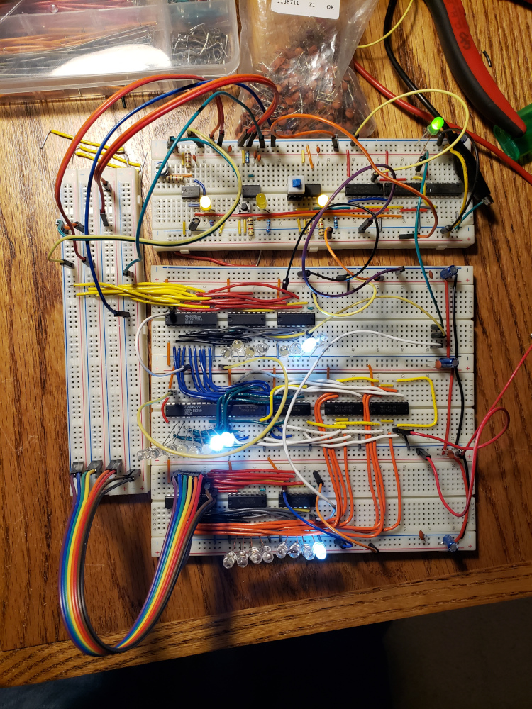
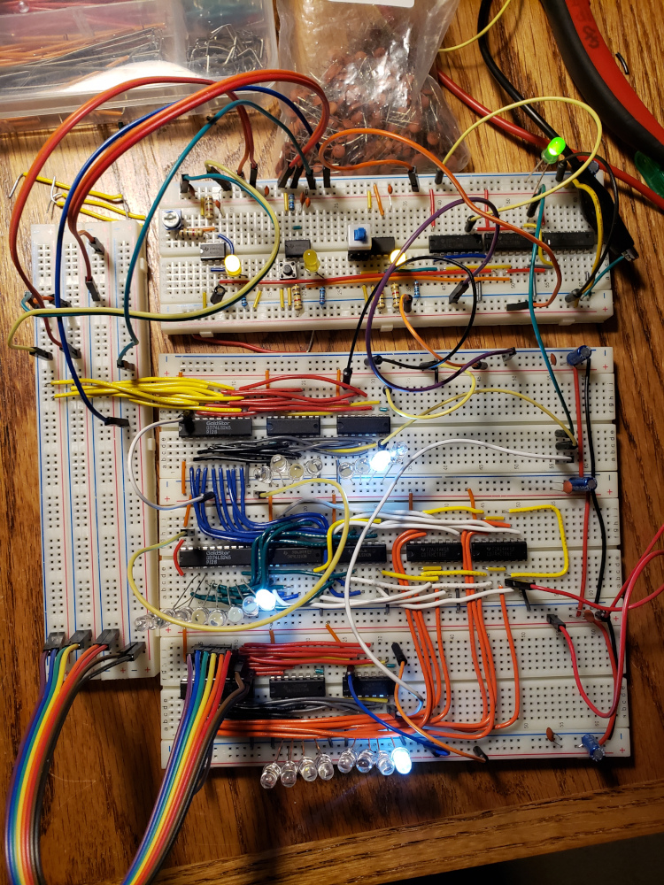
In the image above, register A (the top LED) is displaying the number 2. Register B (the bottom LED) is showing the number 1. The ALU (center) is displaying the sum of the two registers. 2 + 1 = 3

In the above image, I’ve switched to subtract mode. Register A is still 2, register B is 1, and the ALU is showing the difference of 1.
Next, I started building the ram module. This computer will have 16 bytes of ram.

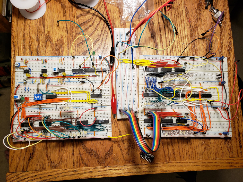
I’ve rearranged the layout a bit. Again this is following Ben Eater’s youtube series, so I am following his lead in the layout.
The left block now contains the clock module in the upper left, the memory address register is below the clock, and the ram module is below that.
The bus is in the center and the right block contains register A, the ALU in the center, and register B on the bottom.