bench safety gear – part 2 – isolation transformer
For the next step in decreasing the chances of killing myself, I’ll be making an isolation transformer. An isolation transformer is a 1:1 transformer where the output is not referenced to ground. So if an isolation transformer is connected to mains, then the output should be 120 volts. You could theoretically touch the live wire (don’t do that) since it is not referenced to ground, so there would be no “return path”, but if you were to touch both hot and neutral, you would get a shock.
I’ll also be putting in some current limiters so if I did happen to zap myself, I won’t take the full brunt of the current.
I’ll actually be using two transformers to construct the isolation transformer. I’ve got two identical UPS transformers that drop 120 volts down to 15 volts. Connected back to back, the first transformer steps the 120 volts down to 15 volts, and the second transformer steps the 15 volts back up to 120v.

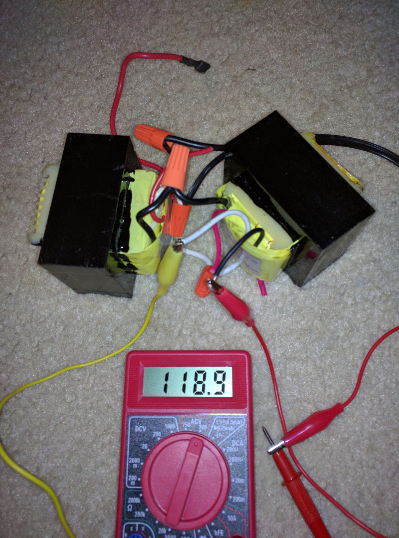
There are some losses in the transformers so the voltage is slightly less than 120. Next, I need an enclosure. The best I could find around the house is an old wooden silverware box. It will work for now.

The box itself is bigger than what I need, but I’ll go with it for the moment. If I can find a variable transformer, I might mount it on the other side. This is how I’ll lay everything out.
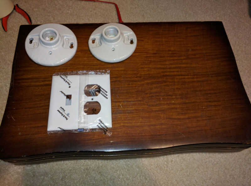
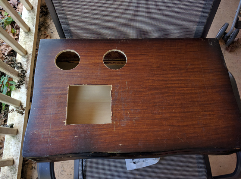
The two light sockets will be part of the current limiting as well as a dimmer switch that will be next to the outlets. I used a hole saw to cut a few holes in the box.

Then a jigsaw to cut out the hole for the electrical box.
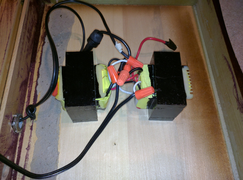
The next step is to start wiring everything up. I brought a two pronged electrical cord in through the back of the box and added an inline fuse. The transformers were only rated for 3 amps, so I put in a 3 amp fuse. I taped up the extra taps and connected everything with wire nuts.
Next, I mounted the light sockets and electrical box and wired them up. The two light sockets are wired inline with the hot wire. The don’t affect operation unless there is a short, then the light up and take the brunt of the current.

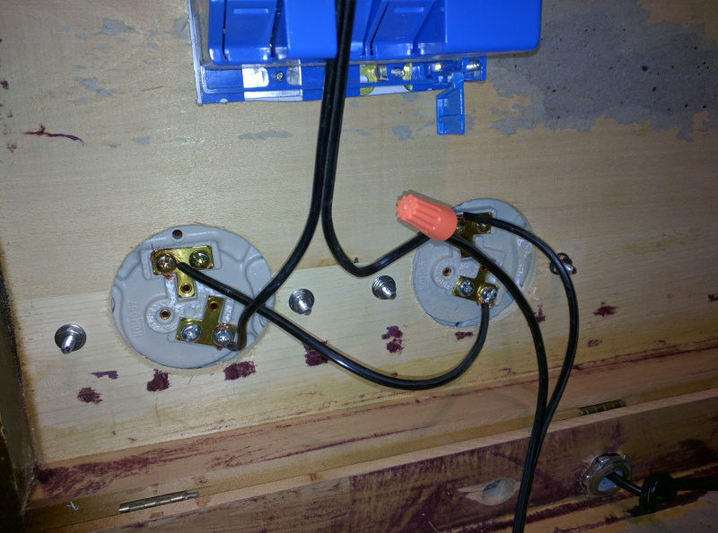
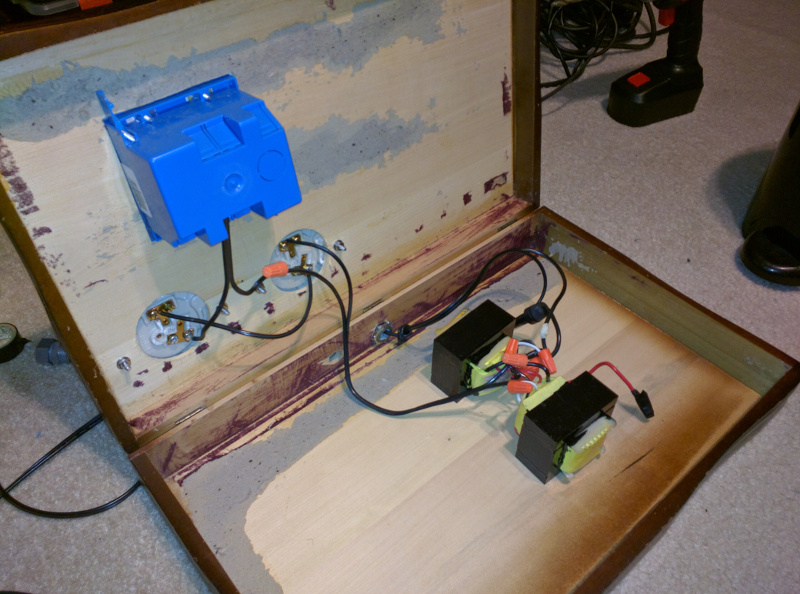
Now, it should be all done.
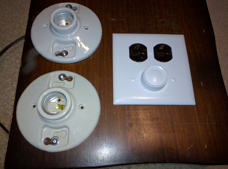
I added some light bulbs and powered it from my gfci box from the previous post. Checking the voltage shows 120 volts on the output, so it is working as expected.
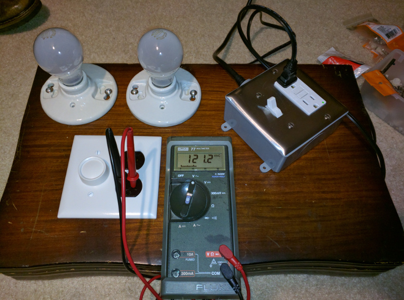
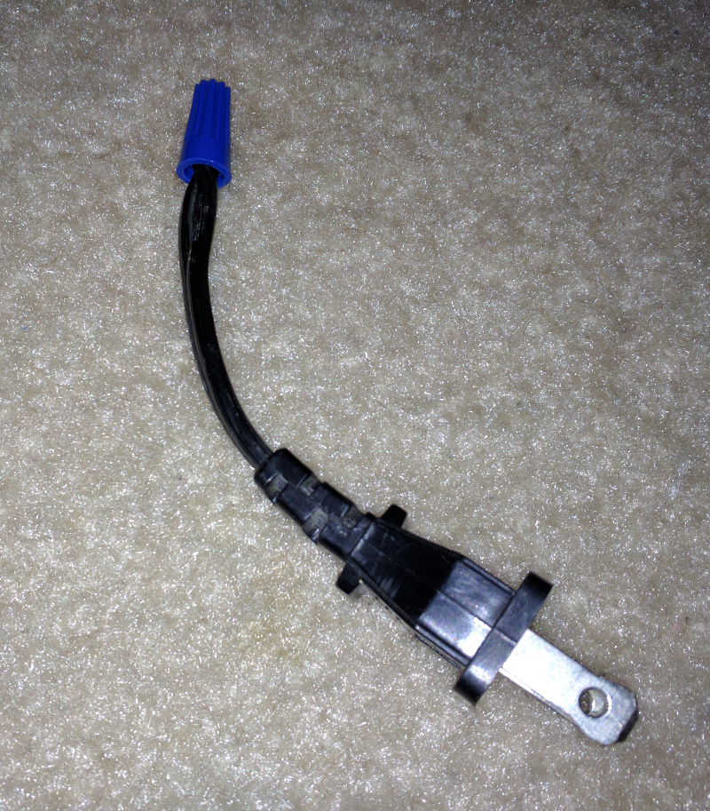
Now, lets simulate a short. I took the end of a two pronged cable and a connected both ends together under a wire nut.
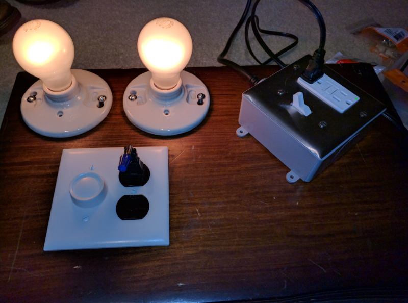
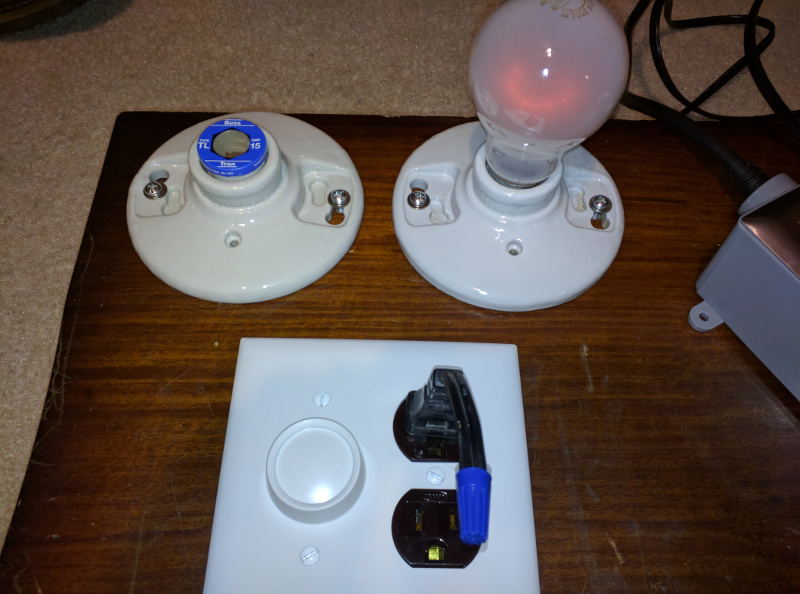
If I were to plug this into a normal socket, I’d get sparks and a blown breaker, but with the current limiter, I just get two glowing light bulbs.
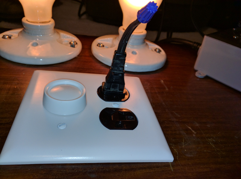
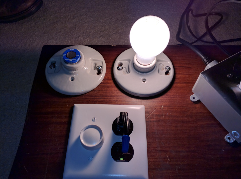
I replaced one of the bulbs with a fuse and tested the dimmer. You can see the dimmer also helps limit the current.
Now, how about grounding the output of the isolation transformer? That is supposed to be the whole point right? If I plug one side of the meter in the outlet and touch the other side to ground, we shouldn’t see any voltage. Lets try it.
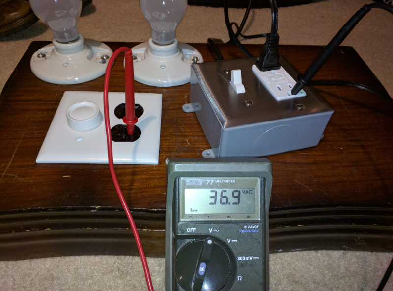
What?! 37 volts? What is going on?
Well, that 37 volts is actually a ghost voltage. Its is caused by capacitive coupling between the energized wires and the non-energized wires. A high impedance meter, like the one I am using will show these ghost voltages. If I had a low impedance meter, it would show a zero reading between the output of the isolation transformer and ground.
So everything should be working as it is meant to and now I should be a bit safer when I’m prodding around a circuit that is connected to mains. Before building one of these yourself, I’d suggest reading all you can and watching a few youtube videos on isolation transformers. They can be just as dangerous as touching ground referenced circuits. Especially if you connect your ground referenced oscilloscope to your isolated circuit, then you’ve just created a path to ground and your scope probably won’t survive that mistake.
Be careful and don’t do anything stupid.