end fed half wave antenna
I’ve been wanting to get back into radio stuff for a while now, but the only antenna that I have up now is a 40 meter dipole. I’ve been wanting to put together a decent multi-band antenna for a long time and finally settled on an end fed half wave antenna.
An end fed half wave antenna, or efhw, is a variation of a half wave dipole, but it is fed from one end. Being end fed, it needs a transformer to transform the higher impedance of the wire to the 50ish ohms the radio is expecting. There are many resources online that explain the details better than I can, so I’d suggest doing your own research if you’d like to build one for yourself. You can start with the links below.
- http://www.aa5tb.com/efha.html
- http://www.hamuniverse.com/randomwireantennalengths.html
- https://udel.edu/~mm/ham/randomWire/.
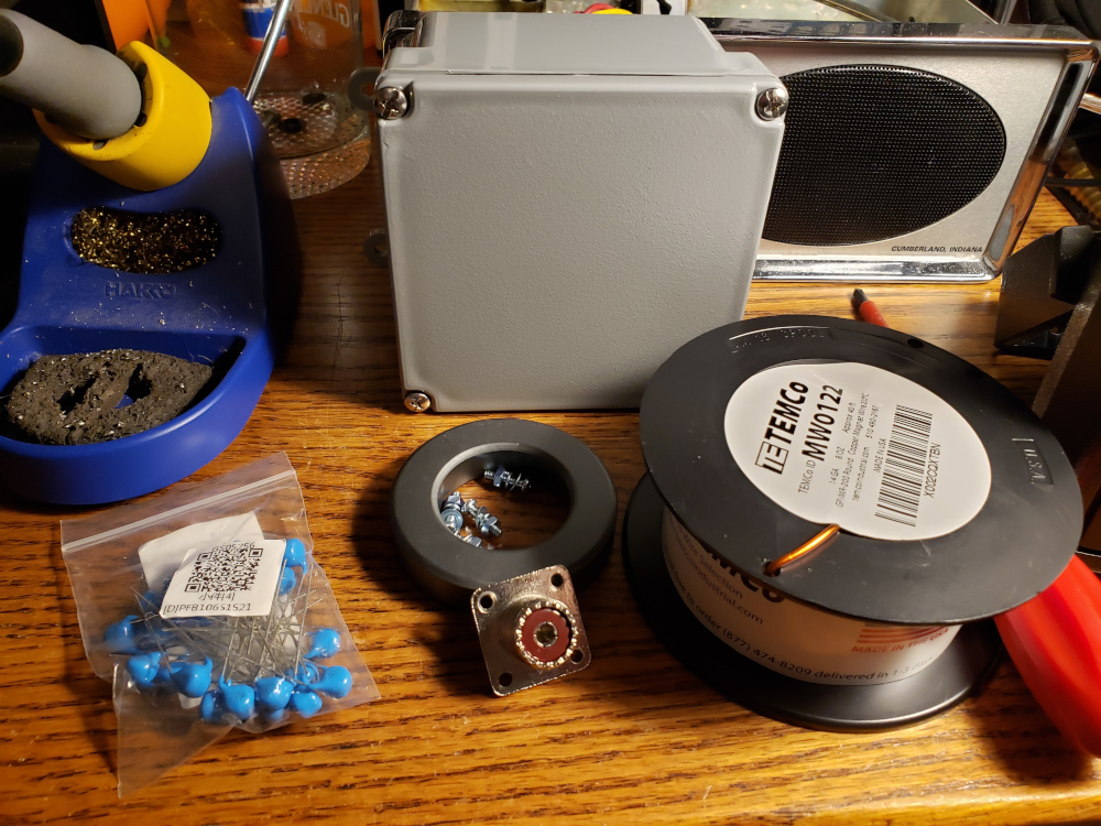
For my build, I started with a waterproof enclosure from the hardware store, a panel mount SO239 connector, an FT240-43 toroid, two 220pf 15KV capacitors, and 14g enameled copper wire, and some hardware to connect it all up.
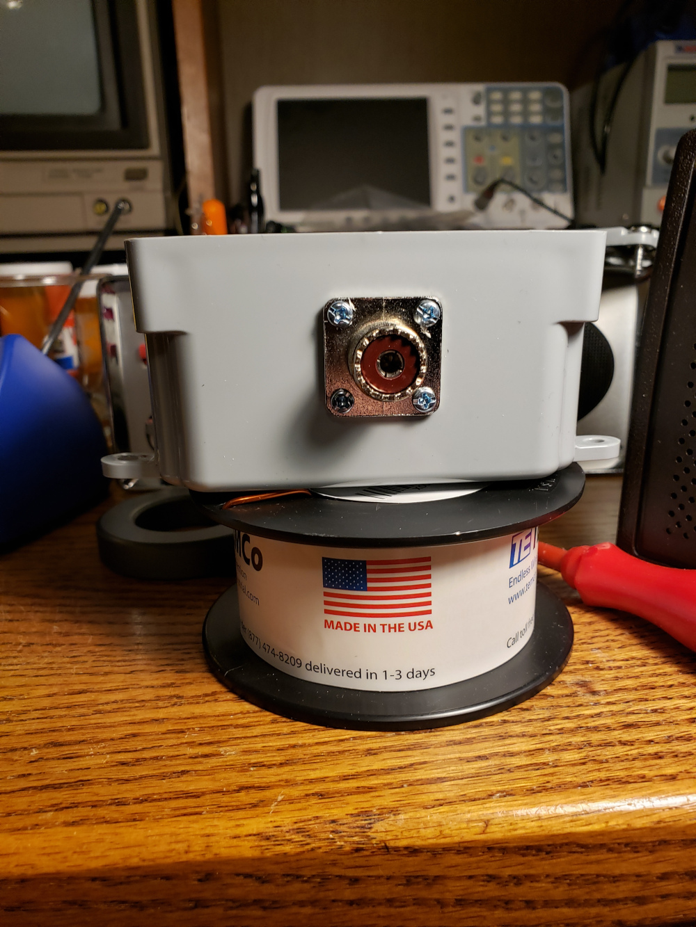
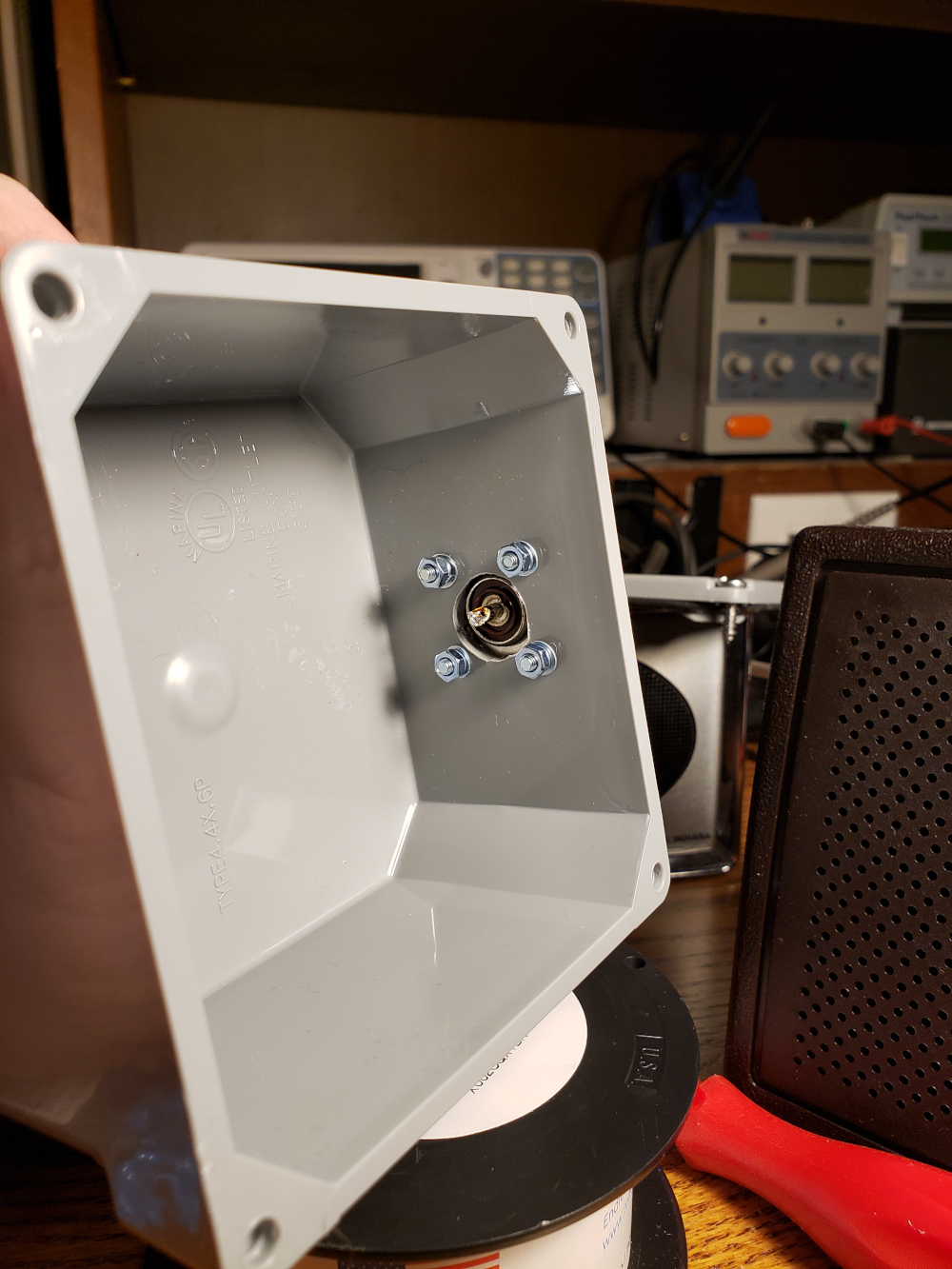
I first mounted the SO239 connector to the box.
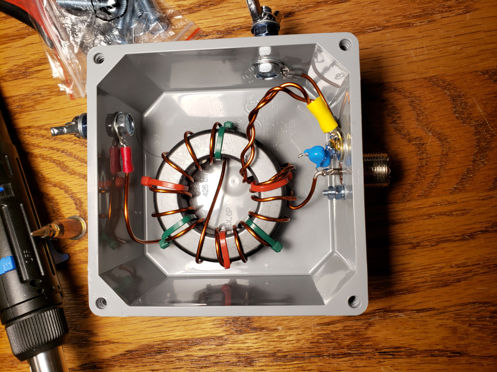
Next, I started winding the transformer. I went with a 49:1 unun to match the unbalanced antenna to the unbalanced feed line. You can find more info here: https://km1ndy.com/diy-491-unun-impedence-transformer-for-end-fed-half-wave-efhw-antenna/
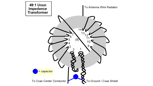
I used the 14g enameled wire and wound it on the FT240-43.
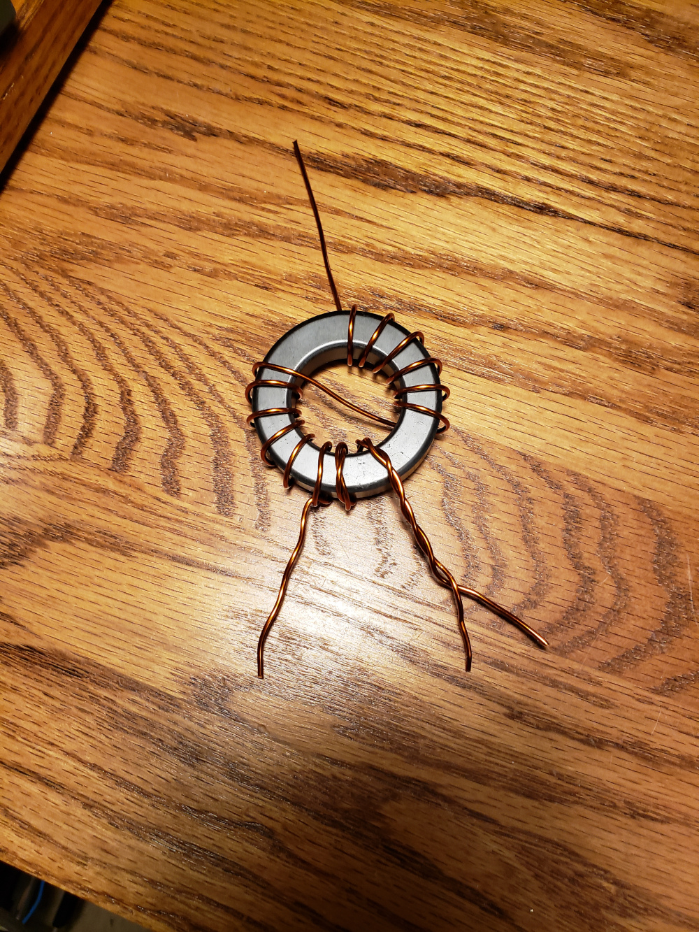
I added some Christmas colored zip ties to hold everything in place.
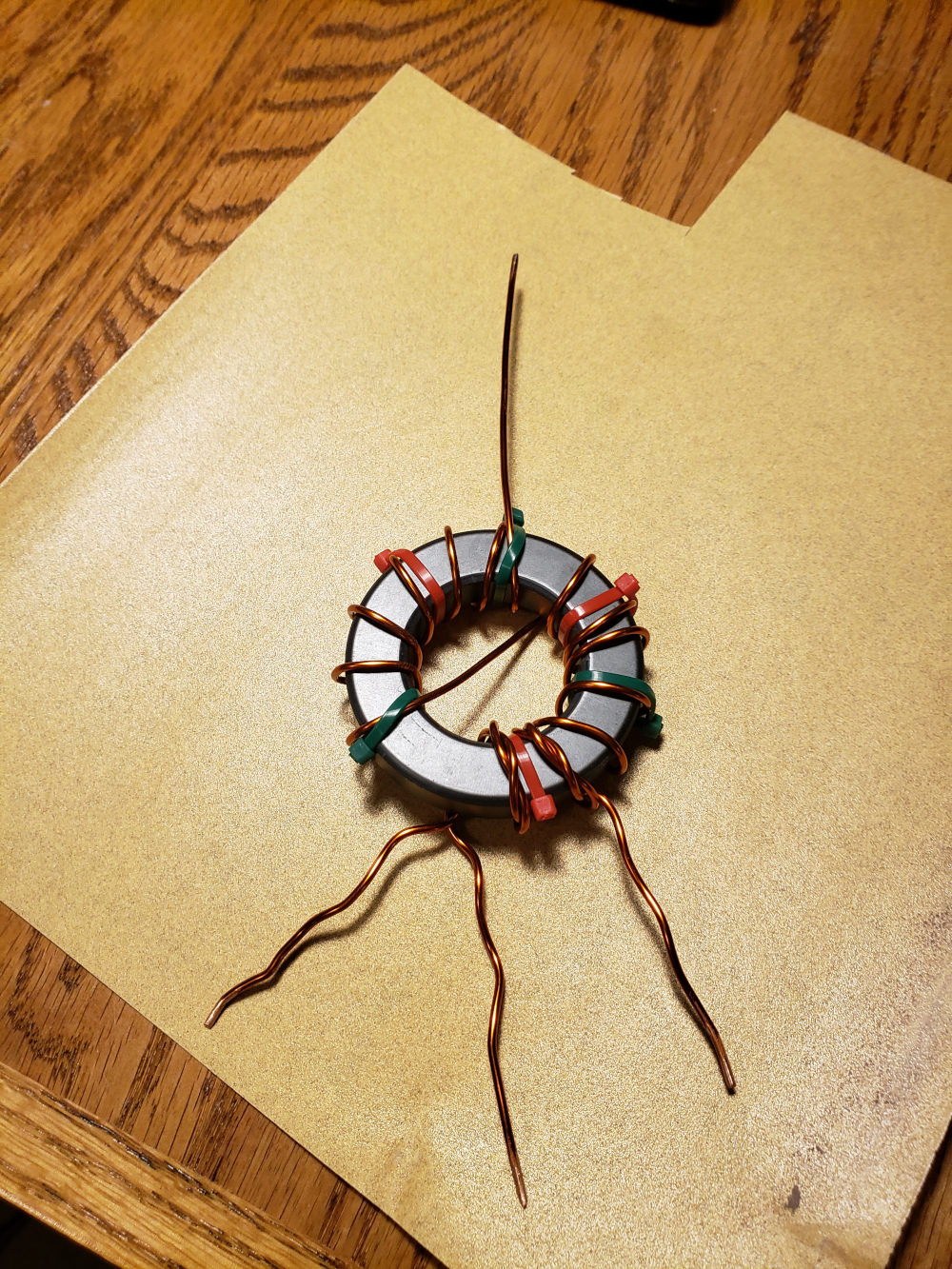
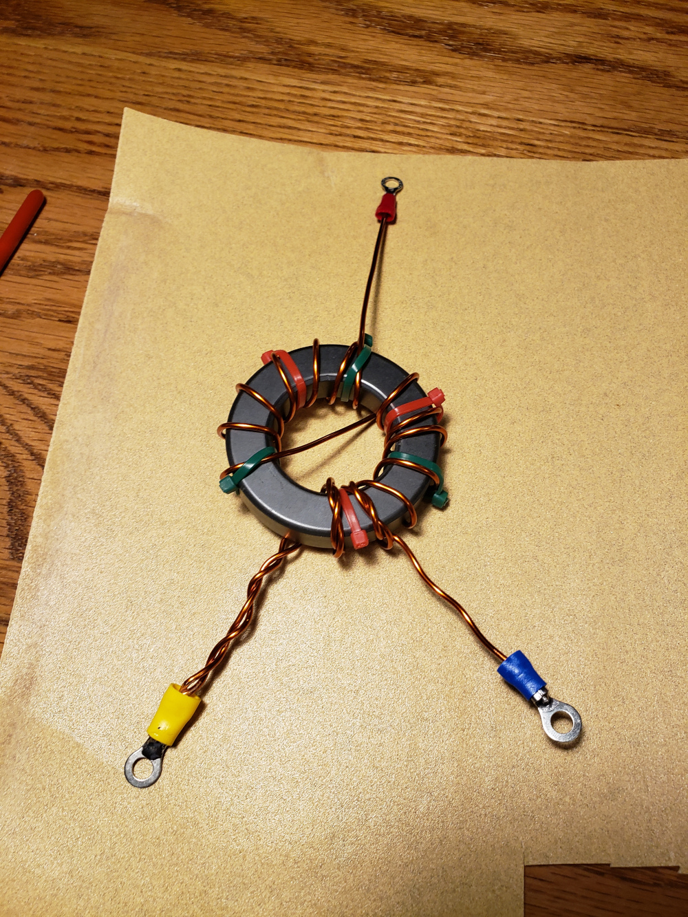
Then I added some ring terminals.
Then I mounted everything in the box.
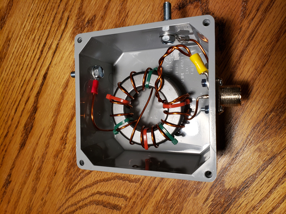
I then added two 220pf capacitors in series between the center conductor and ground.
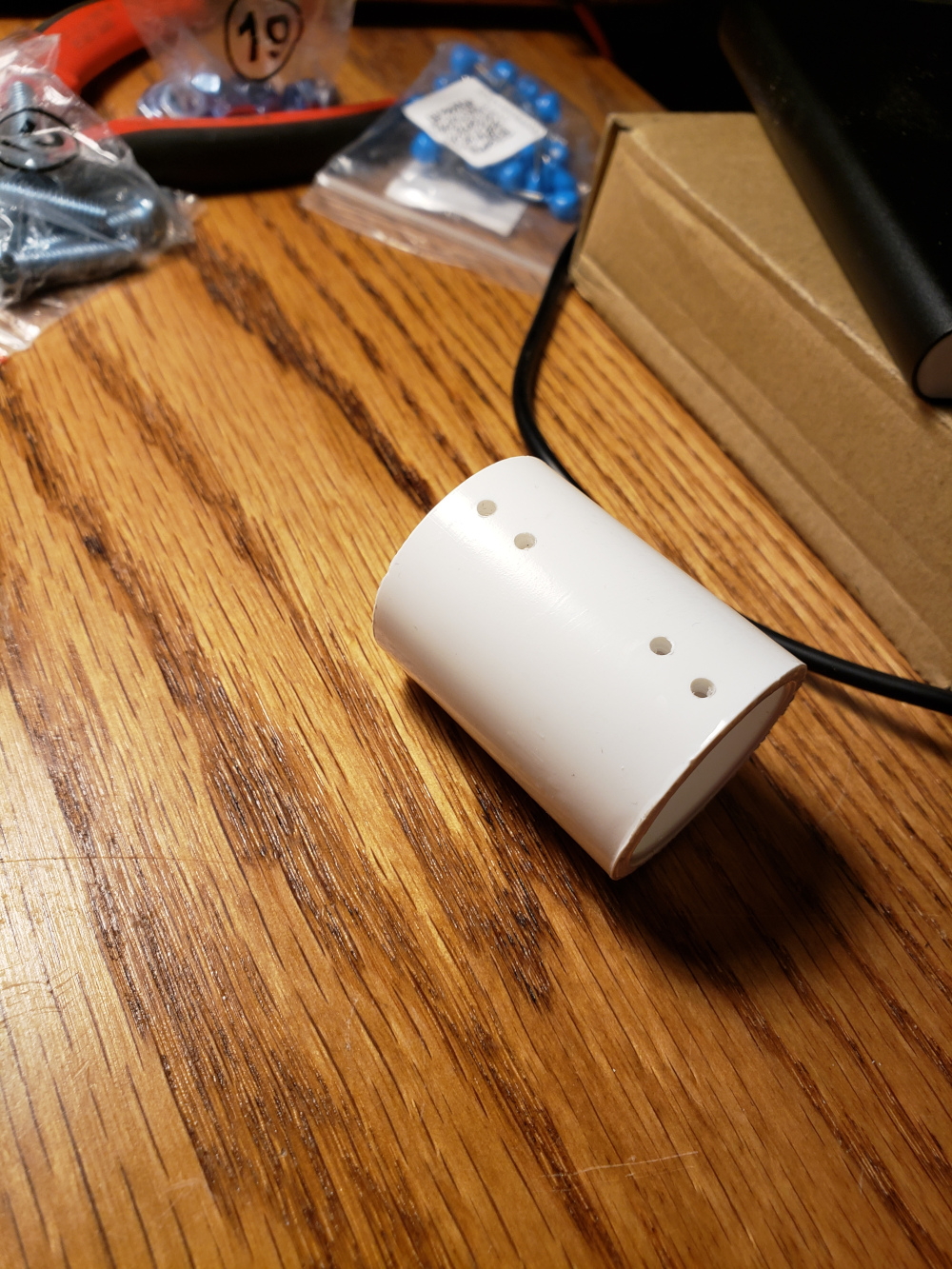
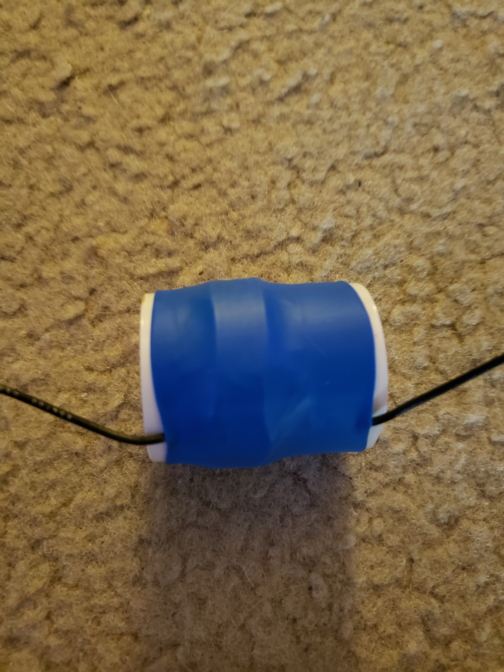
Some of my research showed that a small compensation coil can be added about 2 meters from the transformer to pull down the SWR on the higher bands. I started with a small piece of PVC pipe and drilled a few holes in it to run the wire through.
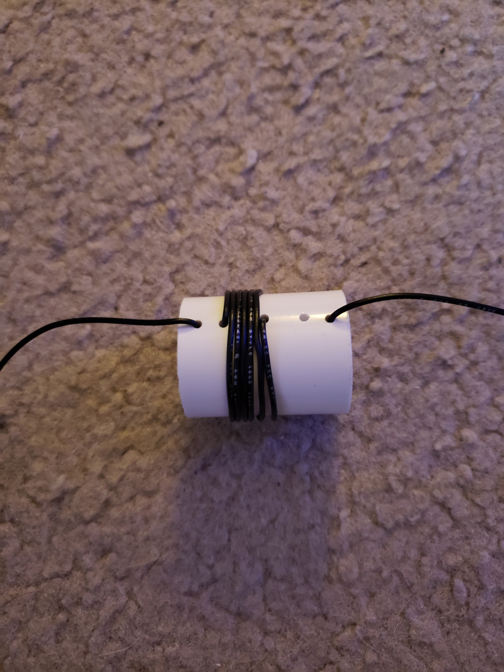
I wound five turns around the pipe.
Then I covered the coil in kapton tape to hold it together.
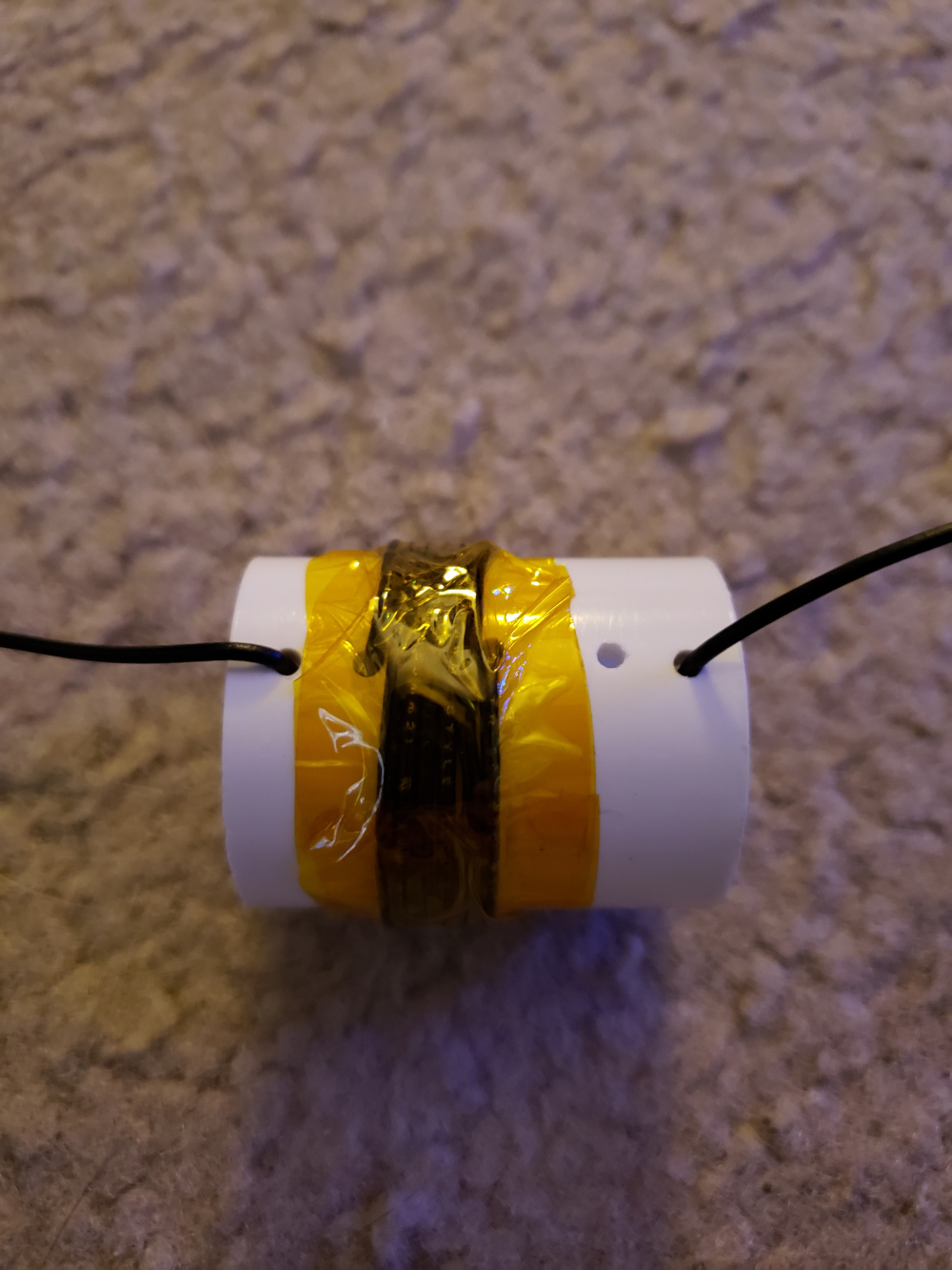
I then used a piece of heat shrink on the outside to hold everything in place.
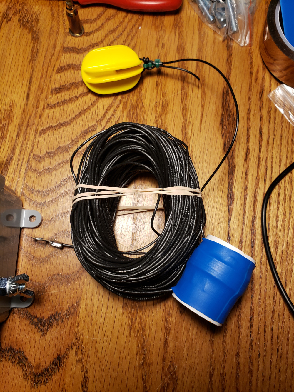
For the antenna wire itself, I used 119 feet of 22g stranded hookup wire. On one end, I added a ring terminal to connect it to the transformer and on the other end, I connected an electric fence insulator.
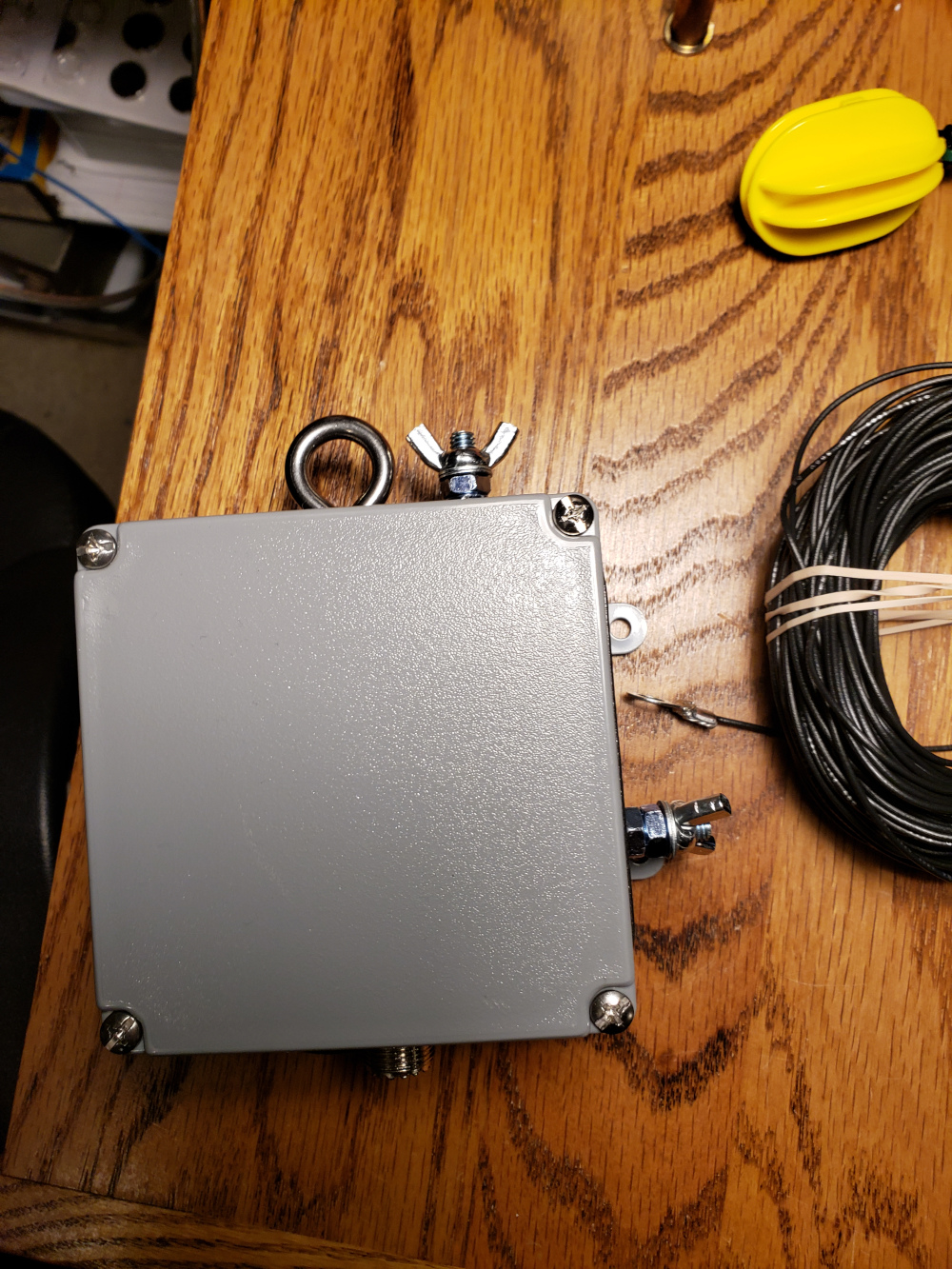
On the transformer, I added a few wingnuts to tighten down the antenna wire.
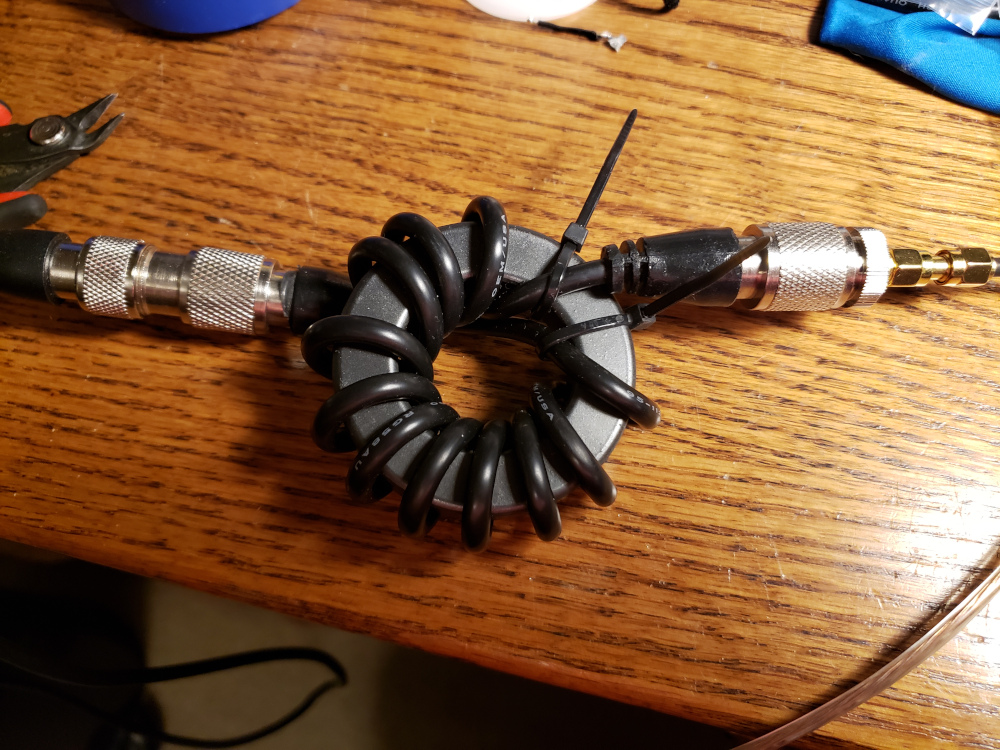
For the last step, I put together a RF choke to use between the radio and the feedline. Since I won’t be connecting a counterpoise, the antenna will use the coax shield as the counterpoise, so the RF choke will keep any unwanted RF from feeding back through the coax.
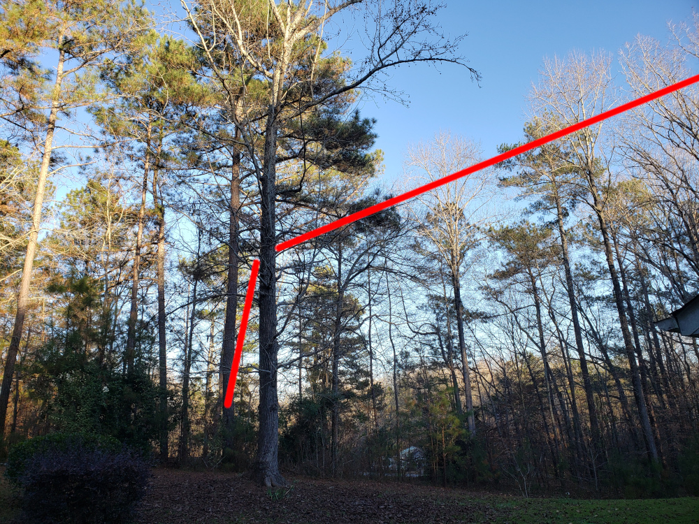
I mounted the transformer on a tree for testing. You can’t really see the antenna wire, but the red line shows the antenna path.
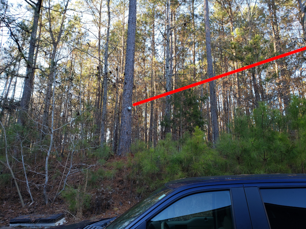
I tossed the line as far up as I could in a tree.
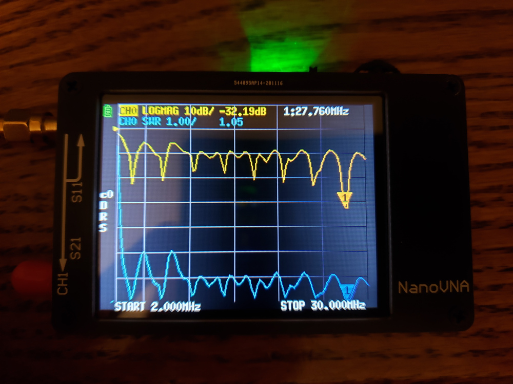
I swept the antenna with a nano vna from 2 to 30MHz and there were nice dips at each band. The worse SWR was 1:1.7 at the top end of 20 meters.
I ran WSPR at 10mW for about 2 hours and got the results below.
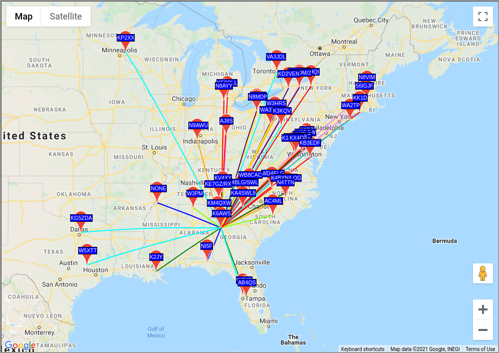
I’m very happy with the result. I was pleasantly surprised that the dips were so perfect across all of the bands and the SWR was low enough to not really need a tuner. Now I just need to build or acquire a decent radio to utilize this new antenna.