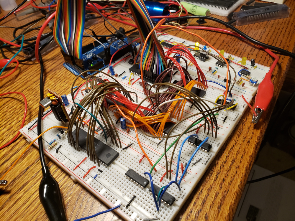
homebrew 6502 computer – part 1
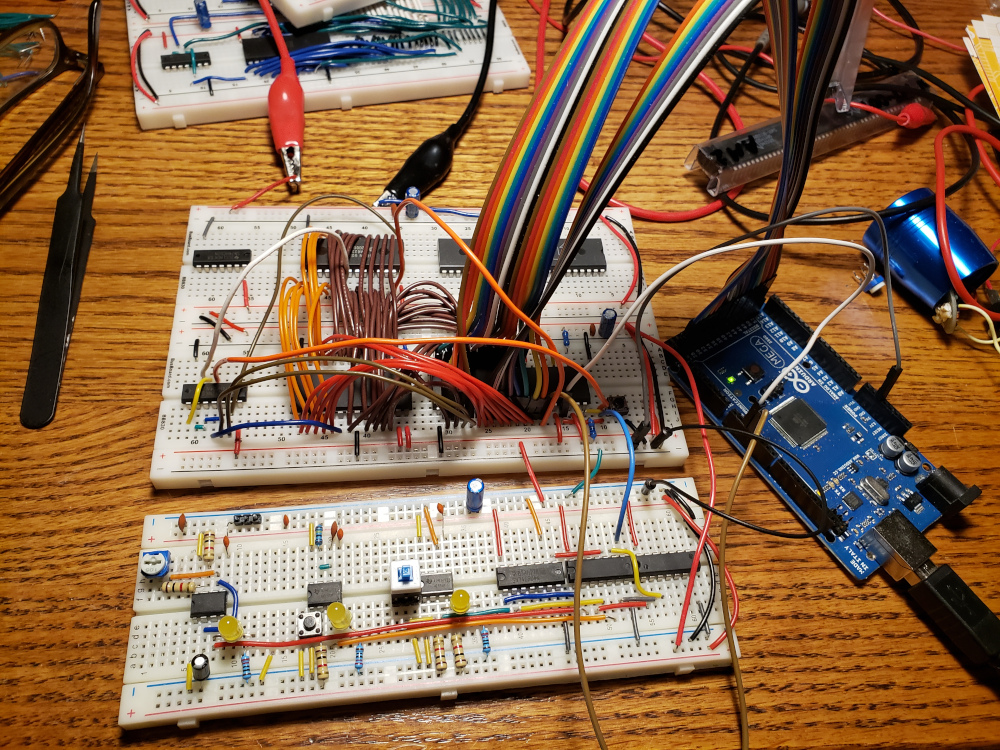
After building Ben Eater’s 6502 computer, I wanted to try my hand at my own version. I wanted to utilize the full 32k of ram and use a real monitor as the display.
I started with a W65C02 processor and an AT28C16 eeprom. I filled the eeprom with nop instructions and set the eeprom to the top of the memory map.
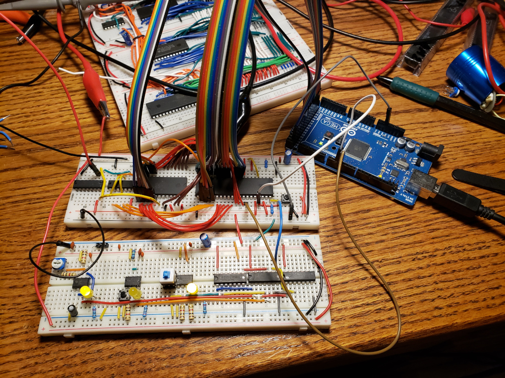
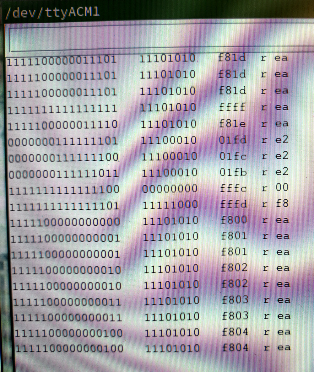
I’m using the same slow clock module and Arduino sketch from Ben Eater to view the address and data buses in real time. You can see the initialization in the screen shot below. The reset vector points to $f800 which is the eeprom full of ea instructions.
I quickly realized that 2k would not be big enough for the ROM. I want to eventually try to get basic running on here. I switched the AT28C16 for an AT28C256. That is a 32k eeprom, but I’m only going to use half of it for 16k.
I then wired up a 62256 32k static ram chip and set up the address decoding. At this point, my memory map looks like:
RAM $0000 – $7FFF
ROM $C000 – $FFFF
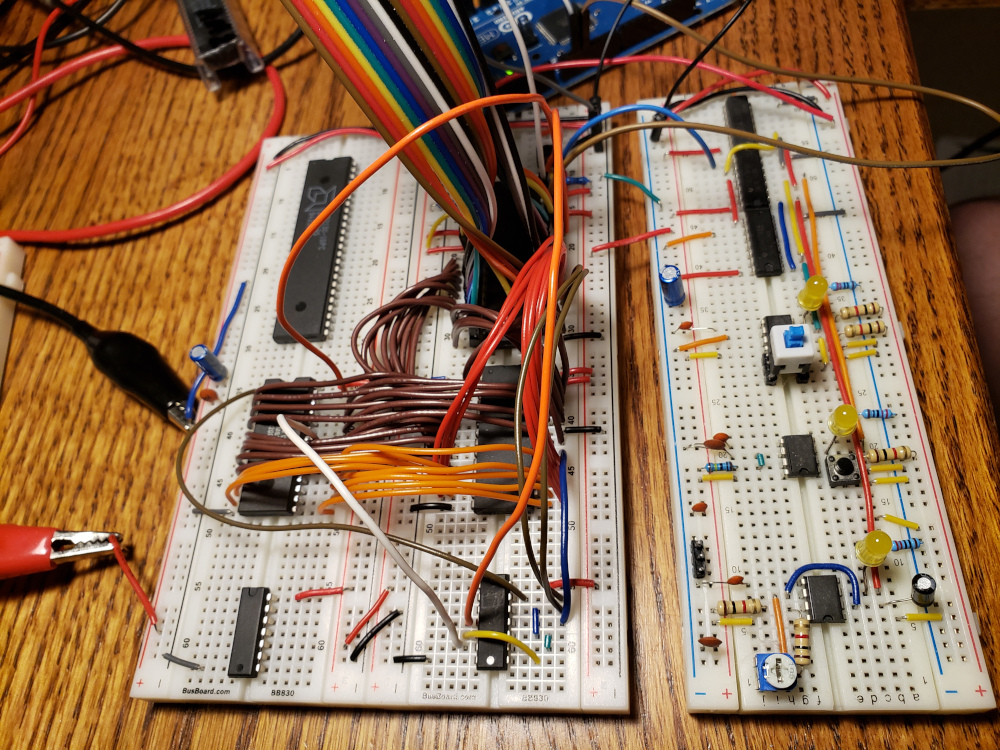
In the image below, you can see the reset vector at $fffc and $fffd launching the start of the rom at $c000.
I’m using the following code to write 0x55 to address $2000 and then reading it back again. Then I write 0xAA to $2001 and read it back to verify that ram is working correctly.
|
|

So now that ram is working, I started looking at the display. I settled on using an MC6847 as the display chip. It has a built in character generator and I can get composite video out. It is relatively simple to interface and I had two in the junk box.
Instead of trying to set up some form of ram sharing, I used a AM2130-10PC 1k dual port ram chip as the video ram. I put it just after ram in the memory map.
RAM  $0000 – $7FFF
VRAM $8000 – $83FF
ROM	 $C000 – $FFFF
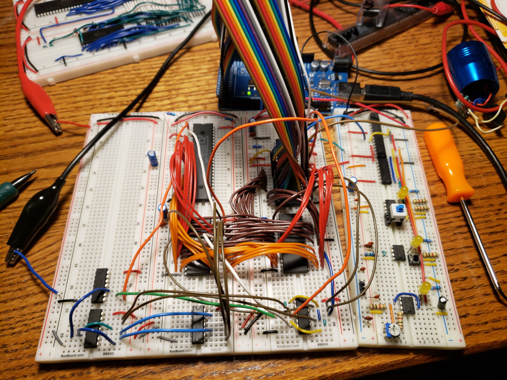
The image below shows writing 0x11 to $8000 and 0x22 to $83FF and reading the values back to verify that VRAM is working.

Now that I have working vram, I wired up the MC6847.
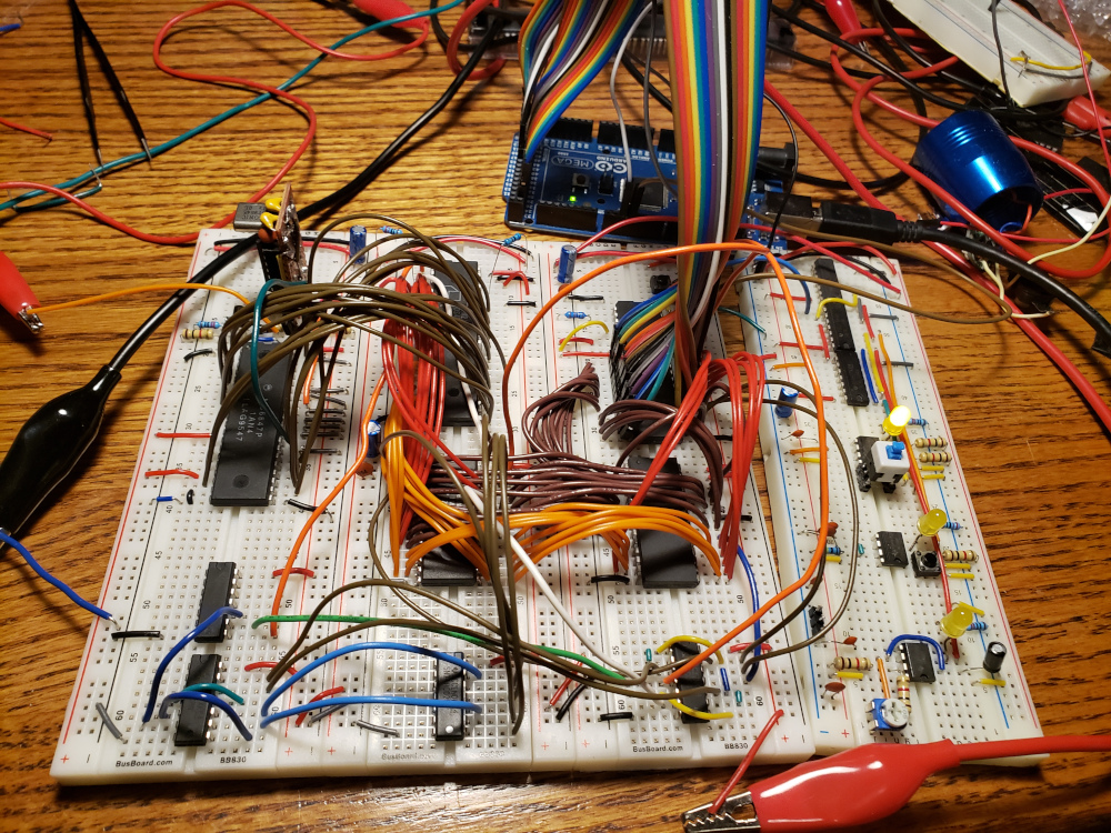
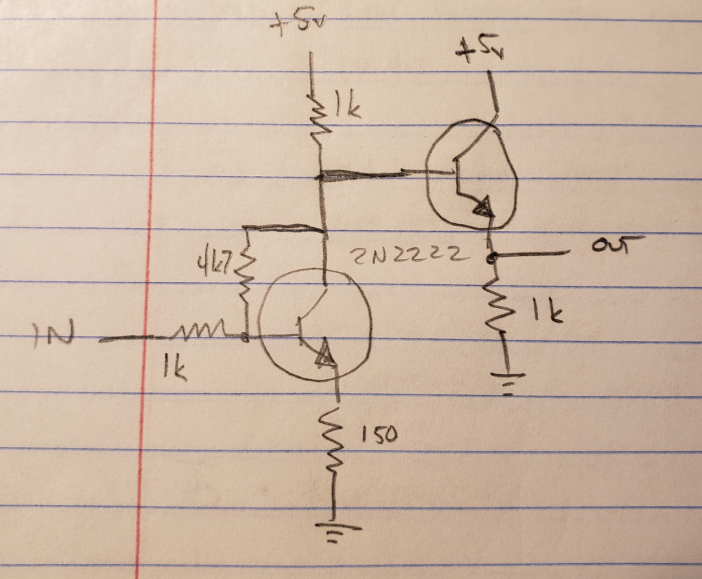
I wired the second port of the VRAM to the MC6847, then I built a 2 transistor amplifier for the video signal.
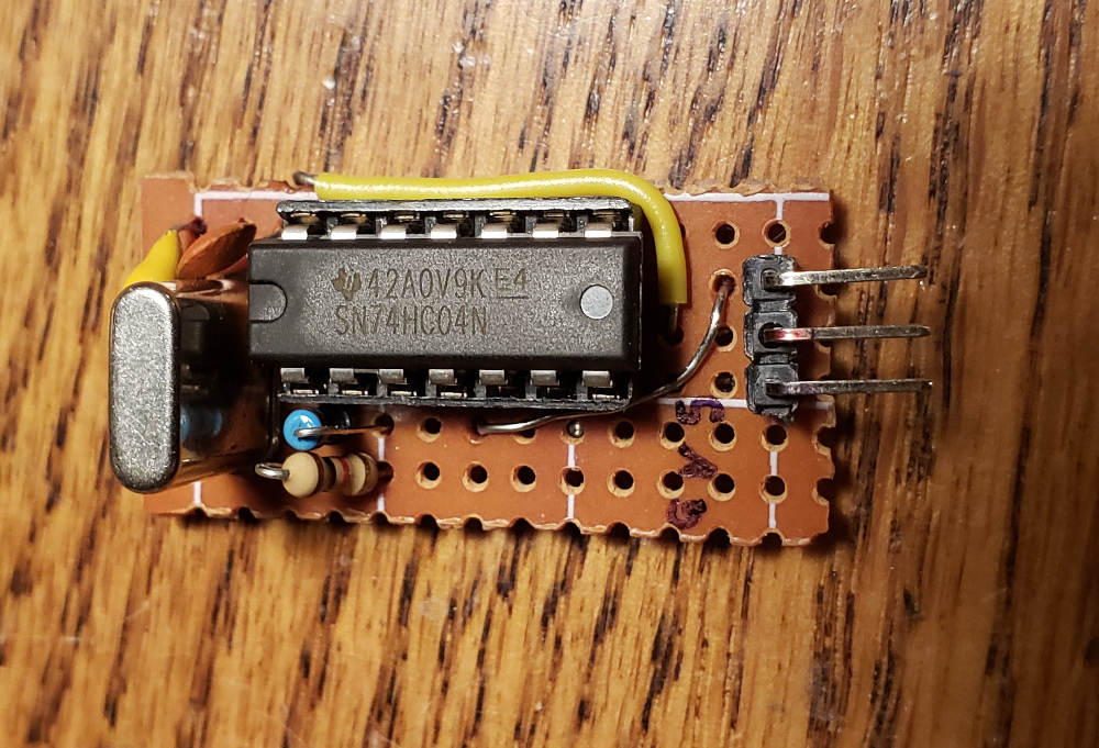
Next I built a 3.579 MHz clock module using a color burst crystal and a 74hc04. I also added a 1MHz can oscillator as the main system clock.
Once it is all wired together, I have a display that can output 512 characters in 32 columns x 16 rows. Each byte of VRAM maps to one character on the screen. The top left character is at address $8000 and the bottom right is $83FF.
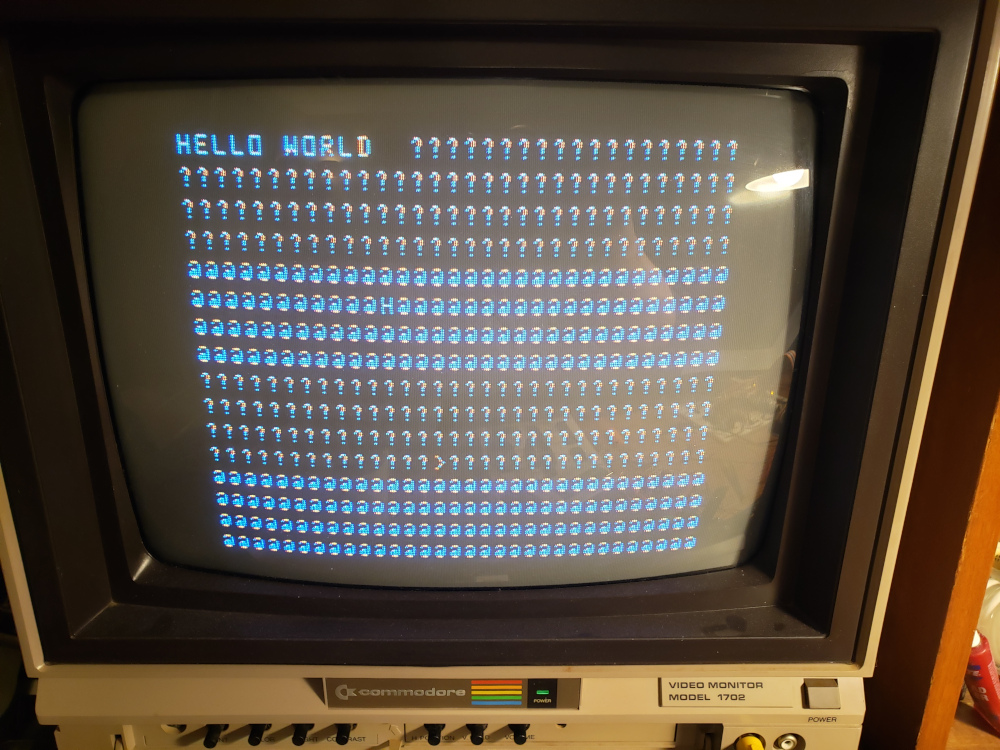
I can now write text to the screen. In the image below, the garbage on the rest of the screen is just the default garbage that was in ram at boot.
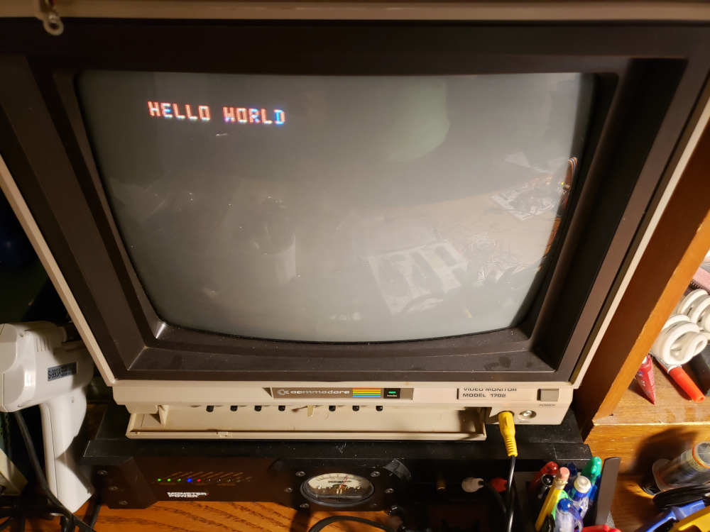
I tweaked the code a little to fill the rest of the screen with blank characters.
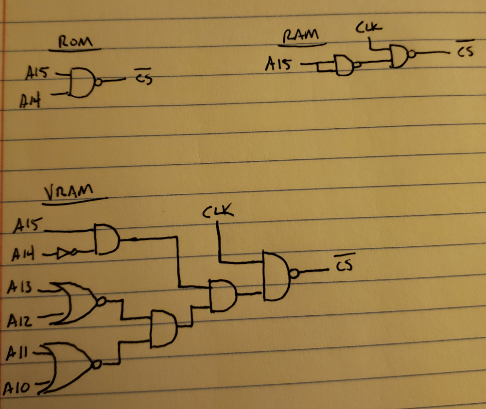
The address decoding so far is in the image below.
Next, I’d like to write some display handling code. I also need to add a keyboard interface to make this thing somewhat useful.
