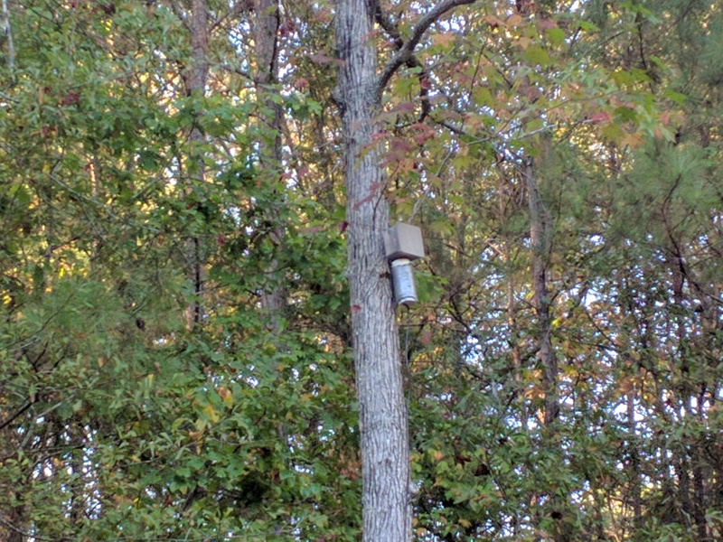
new dipole
Following my antenna analyzer project, I figured I’d put up a better antenna now that I have some rough way to measure resonance. At first, I was looking to make a 40m/20m multiband dipole. Using some spare rg-6 coax and some 14 gauge stranded AC line, I measured out my wire and constructed the dipole.
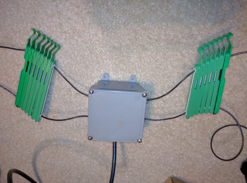
This is what I ended up with. A waterproof box with the 40m line on top, the 20m line below it, and the rg-6 entering from the bottom. Inside the box was a toroidal balun and those green things are old hard drive brackets I was planning to use as spacers. I put out the antenna and tested it with my antenna analyzer and swr meters and was getting some weird readings. I left the lines a little long so I started trimming them down. I kept trimming and trimming, but was still getting weird readings until I knew that I trimmed too much. This was my first multiband dipole so I may have done something wrong. I never did get any decent measurements, so I ended up scrapping the whole thing and I started over from scratch.
This time, I went with just the 40 meter band with the option to add other bands later. I also picked up a larger box and instead of a toroidal balun, I used an ugly balun on a piece of 3″ pvc. I also took more pictures this time around.
First, I took the PVC and cut it down to about a foot long section and drilled in some holes to feed in the coax.
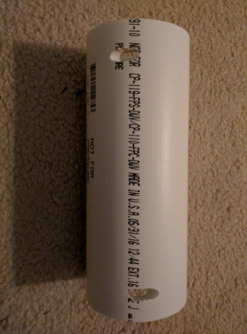
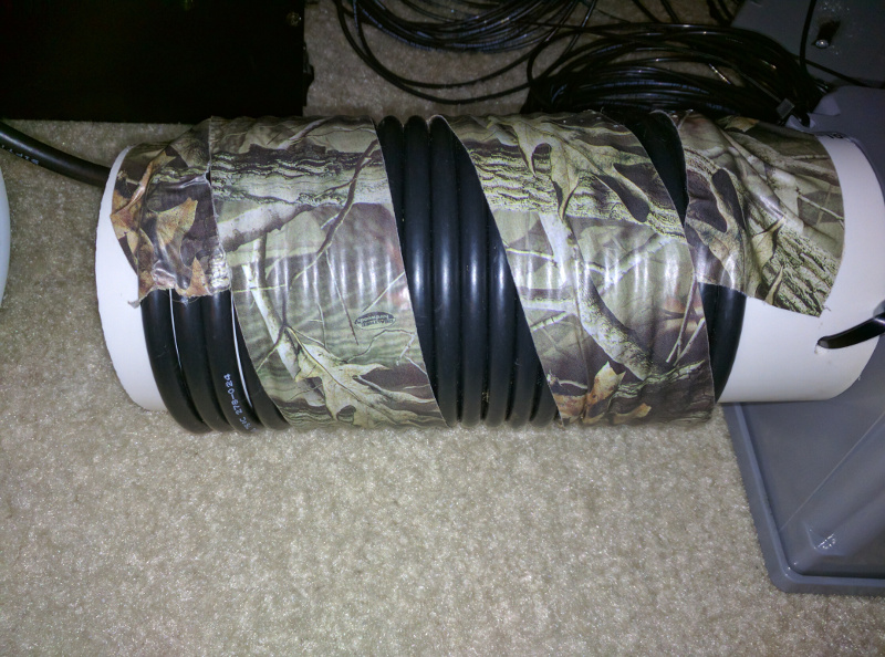
I used the same rg-6 from before and wound it through the pvc. The coil should consist of about 18 to 21 feet of coax. I ended up with 21 turns.
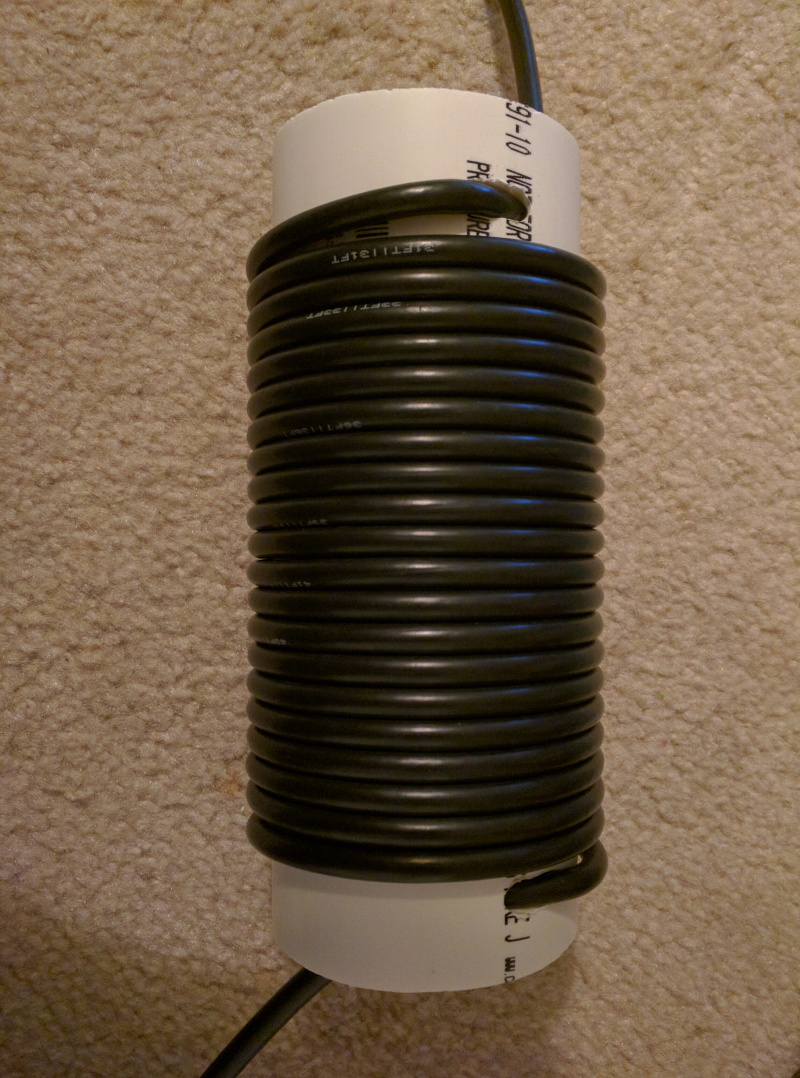
I taped up the coil to hold it in place. I eventually taped around the whole coil.
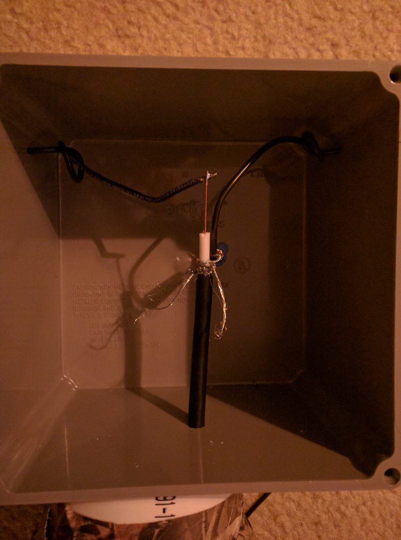
Next I drilled out the waterproof box and ran the stripped rg-6 and 14 gauge AC line into the box. I tied knots in the AC line for strain relief and then soldered the center conductor of the coax to one end of the AC line and used a wire nut to connect the coax braid to the other end. I twisted off several other sections of the braid so I can add more bands later if I wanted.
Next, I sealed up around the cables with silicone and started testing. I hung the antenna and tested with the antenna analyzer.
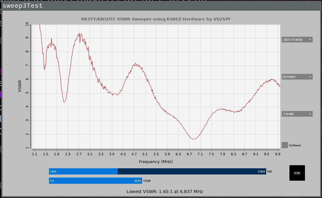
I don’t think my analyser is particularly accurate, but it shows that the antenna is resonant at 6.9 – 7.0 MHz, which is close enough. I also checked it with two SWR meters and was at 1.1:1 on one and 1.2:1 on the other.
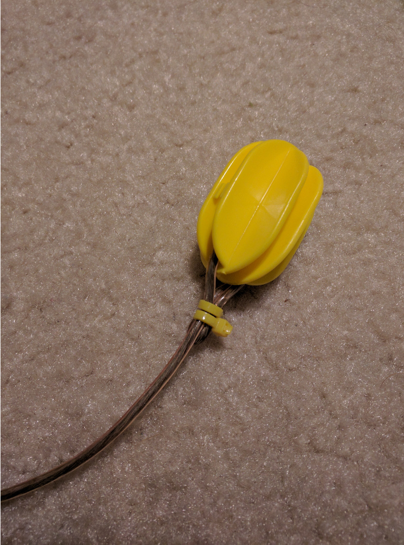
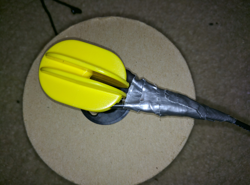
Now that the measurements are looking good, I can permanently fix the ends. For the end insulators, I used electric fence insulators that I picked up from the local farm supply store.
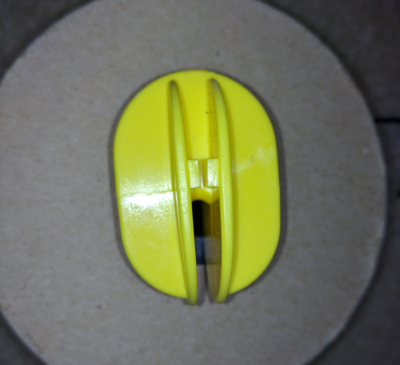
I added some heat shrink on one end, but it was more of a hindrance than a help, but I wrapped and soldered the end back on itself and wrapped it around the insulator. I taped up the ends with duct tape to somewhat waterproof it.
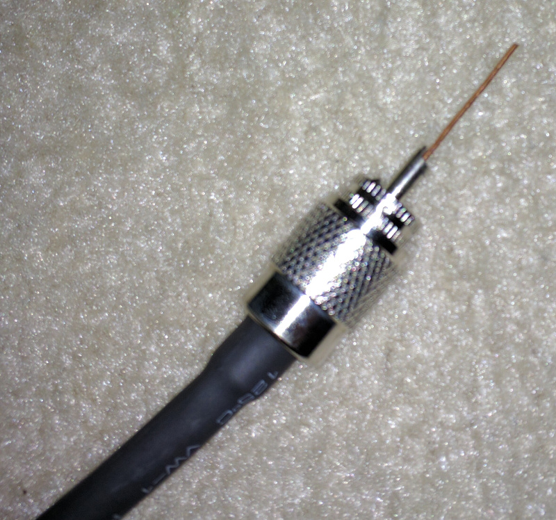
Next, I added a PL-259 connector to the end of the rg-6. The best way that I have found to do that is to strip the coax and then wrap about 5 to 6 turns of duct tape on the insulation where the cable was stripped. Don’t forget to add your heat shrink before the connector.
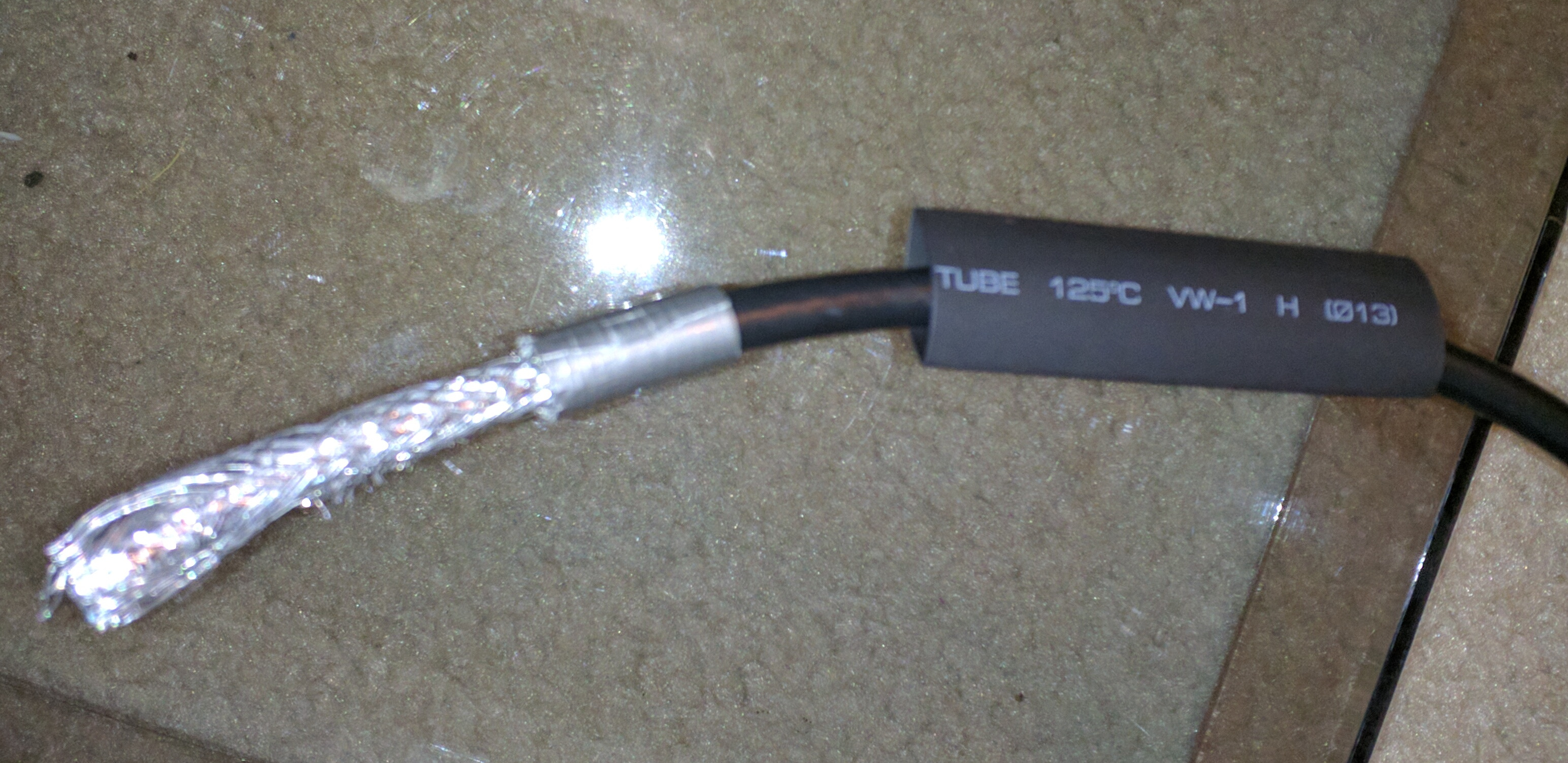
Next, fold back the braid and strip the dielectric to about 1/4 inch above the braid.
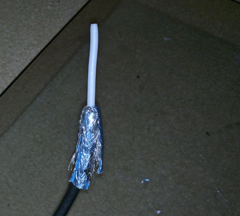
Then add your connector. The duct tape should fatten up the cable enough for the screw on connector to bite into it. Next, I shrank down the heat shrink on the end and soldered in the center conductor.
I hung the antenna about 15 feet up a tree on top of a hill next to my house which makes it about 30 feet or so above my driveway. That is about the best location I have and it seems to be working well. The furthest station that I have heard so far is about 2000 miles away. I haven’t tried making any contacts yet. I still only have a ~5 watt qrp cw transmitter and I’m still getting up my morse code speed. I may put out a CQ and see if I show up on the reverse beacon network just to see how well it is working.
