nixie tubes
I finally received a batch of 1n-14 nixie tubes that I purchased from ebay for a future clock project. The tubes need a power supply that can supply 170 volts DC, which I didn’t have, so I built one.
I came across a few switching designs online and I settled on the one from here, mainly because I had most of the parts on hand. I made a few changes from the schematic which I’ll detail below.
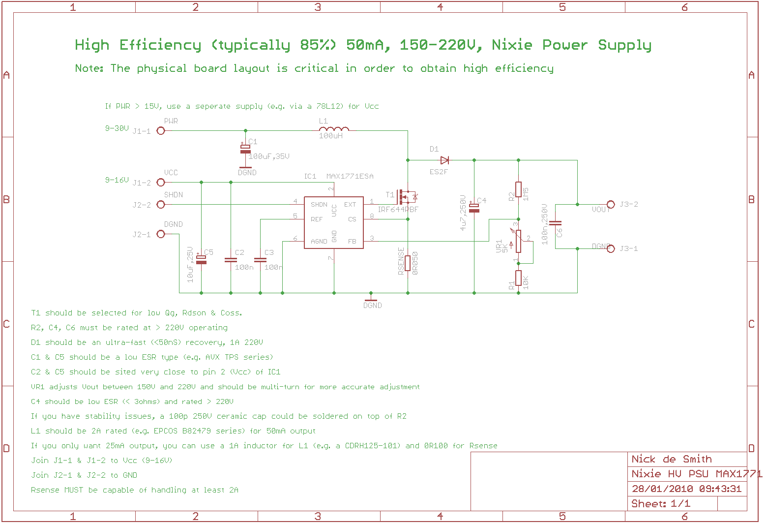
My changes (based mostly on parts that I had available):
L1 = 150uH
D1 = BAV21
T1 = IRF610
RSENSE = 1 ohm
C4 = 10uF
C6 = 470nF
VR1 = 10k ohms
I built the circuit on a piece of perf board with screw terminals for the inputs/outputs.
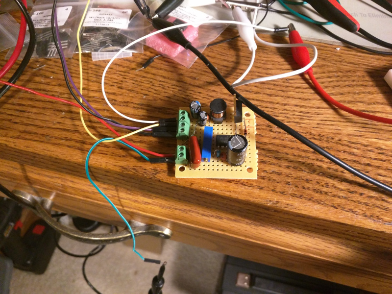
It worked pretty well from the start. I was getting 181.5V DC during my first run.
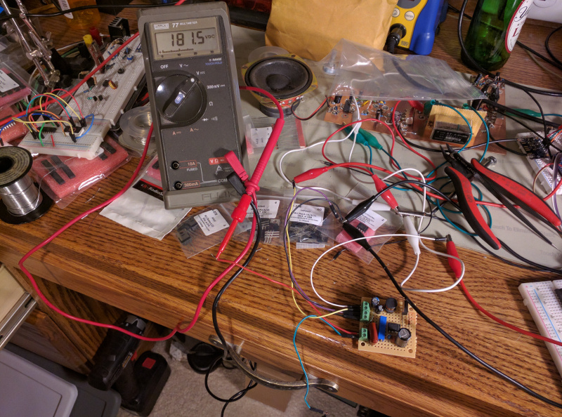
From 3.6 volts in, I was getting the full voltage. I will run it on 12 volts during actual use. (Ignore the messy desk.)
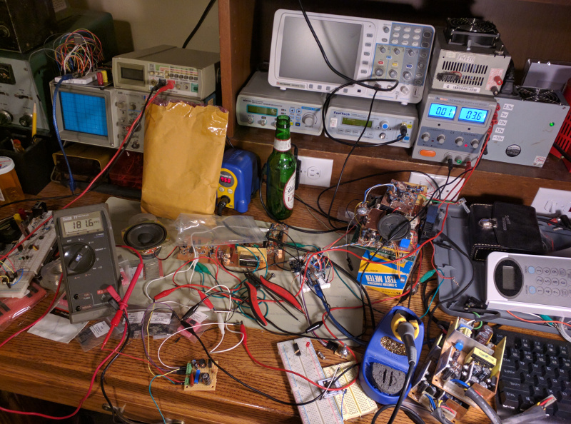
I plugged one of the tubes into a breadboard and just hardwired the power supply to the anode through a resistor and one of the cathodes and tried it out.
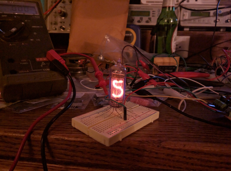
It works!
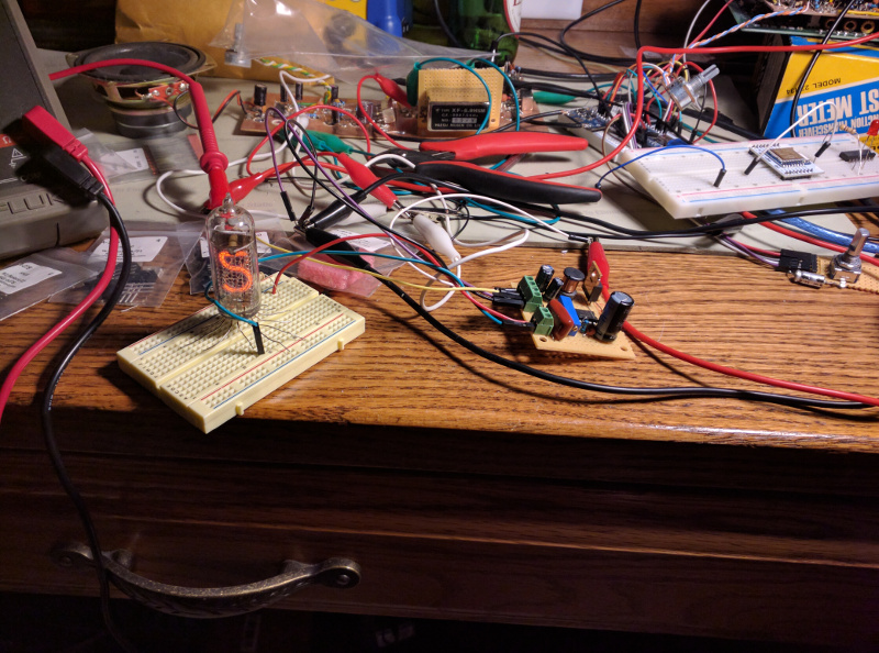
Now, to give it some logic. I wired up an MPSA42 transistor for each cathode and connected them to a bcd to decimal converter. I then put together a quick arduino sketch to scroll through the numbers. It was a bit overkill, but its what I had laying on the desk at the time.
https://awsh.org/wp-content/uploads/2017/10/nixie_count.webm I just about ran out of jumper wires.


Well, the power supply seems to work and the tubes look okay. Next step is to design and build an actual clock.