ads-b coaxial collinear antenna
After I killed my homebrew upconverter, I went back to messing around with ads-b and dump1090.
The little antenna that came with the rtl-sdr dongle worked okay, but I wanted to build a better antenna to see if I could get more range. I looked online and found quite a few pages on coaxial collinear antennas and I had everything I needed to build one, so I figured I’d give it a shot.
Most of the info I gathered was from here, which is probably a better guide to follow, but I will document my experiences here.
First, to calculate the length of each element, we need to find the wavelength of the signal. The wavelength can be found with the formula λ = v/f where v is the velocity of the signal in meters per second (300000000 meters per second) and f is the frequency in hertz (1090000000 Hz for ads-b).
Using the formula above, we get a wavelength of 0.275 meters or 275 millimeters.
Before we can cut our elements, we have to take the velocity factor of the cable into effect using the formula, L=0.5λ * F where F is the velocity factor of the cable.
I’m using scrap 75Ω RG-6 and I have no idea what the velocity factor is, so I used the measurements from the balarad.net article which is 0.83.
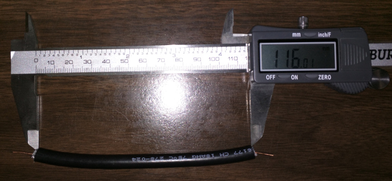
So each element of the dipole will be, 0.5 * 275mm * 0.83, which is 116mm.
Now we can start cutting the elements. I decided to go with 12 elements, but I’ve seen others with 8 or 16 or even 24. Cut them to about 125mm to start with.

Measure out 116 mm in the center and then strip the ends.
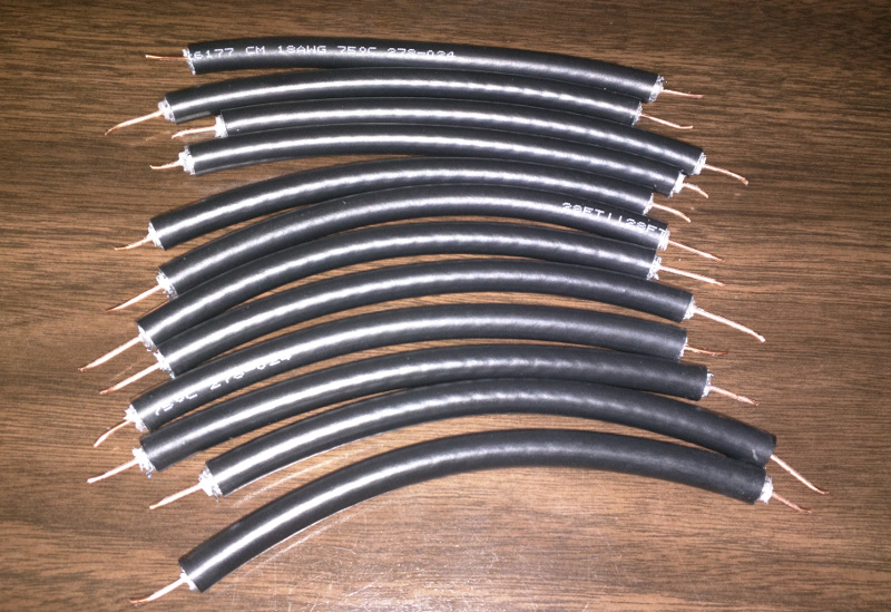
Next, to assemble the elements, use a piece of electrical tape and poke each center conductor through it and into the outer braid of the next element.
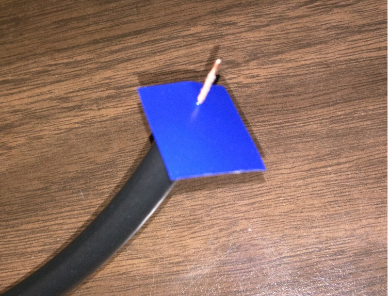
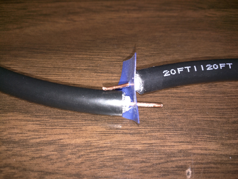
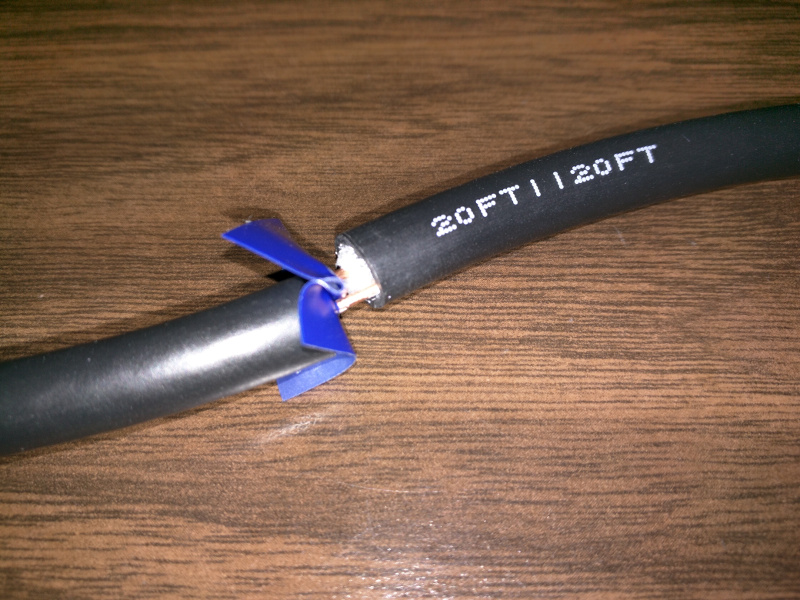
So now, the first elements, center conductor should be connected to the second element’s shield and vice versa. Check the connections with a multimeter and make sure there is no continuity between the two center conductors.
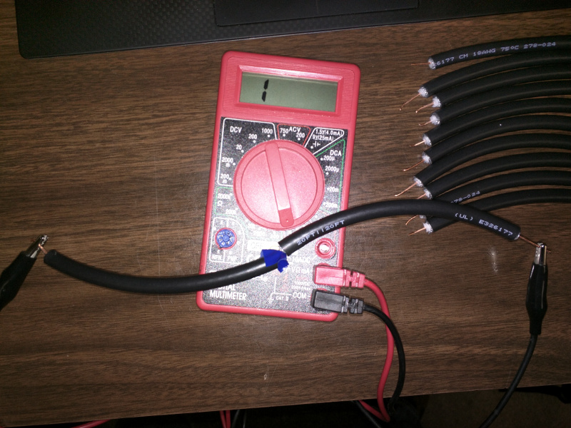
Continue assembling the rest of the elements in the same manner. Test continuity with each joint. The continuity should alternate with every other element. Then secure each joint with electrical tape.
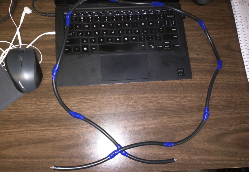
Once all the elements are connected, the center conductor on one end should be connected to the shield on the other end.
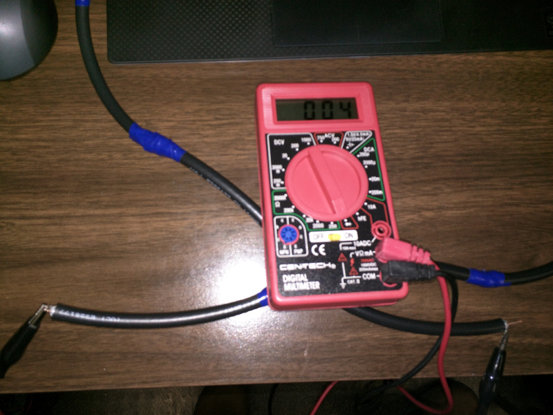
Next, on one end, solder in a 75Ω resistor between the shield and the center conductor.
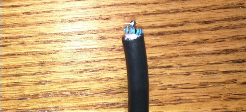
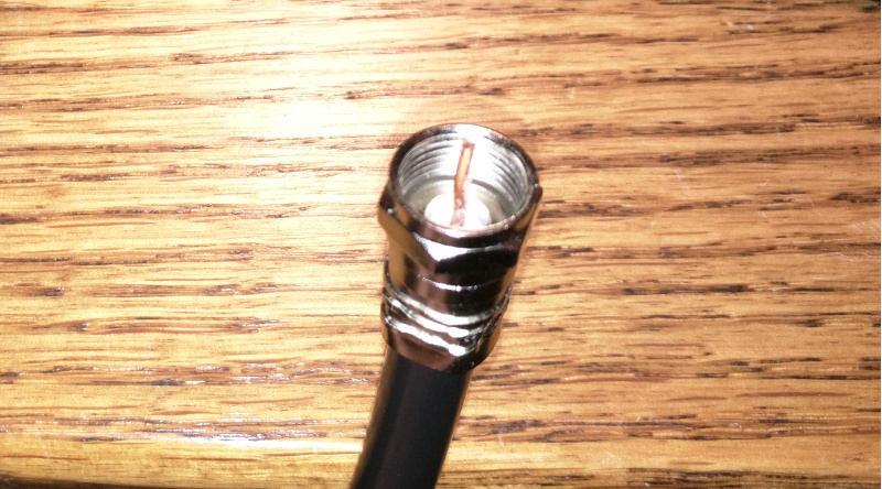
On the other end, I went with a standard F connector since I have an F connector to MCX adapter.

So, how were the results?

Honestly, not that great. The antenna performed almost exactly the same as the little antenna that came with the dongle. I was using scrap coax and my measurements may not have been the most accurate. I will try to add an amp to it or i may just get some better coax and try to make a new one, but if nothing else, it kept me occupied for an afternoon.