rover project – part 1
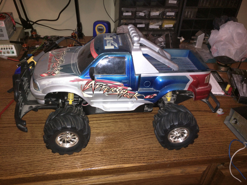
I am currently waiting on parts from China to continue working on my radio receiver, so I thought I’d start working on a robotic rover. I’ve picked up several remote controlled cars from the thrift store and I have been meaning to turn one into some kind of autonomous vehicle that can roam around the yard. Here is what I am starting with. I think I paid $1 for this truck without the controller.
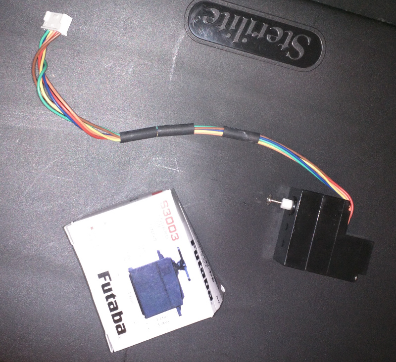
The main controller board was fried (my fault from previous tinkering), so I couldn’t control the steering. The truck uses one of those weird six pin quasi-servos that are in most of these old rc cars. I could still control forward and reverse by applying voltage straight to the gate of the main transistor and toggling a relay on and off to switch from forward and reverse, but since I couldn’t control the steering, I decided to switch out everything for an arduino with a motor controller and standard hobby servo for the steering. Here is a picture of the chassis with the original controller board attached.
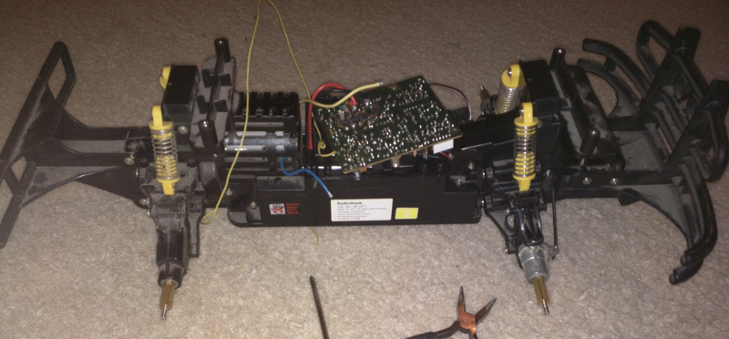
I removed the controller board and took the front end off to figure out how to replace the steering servo.
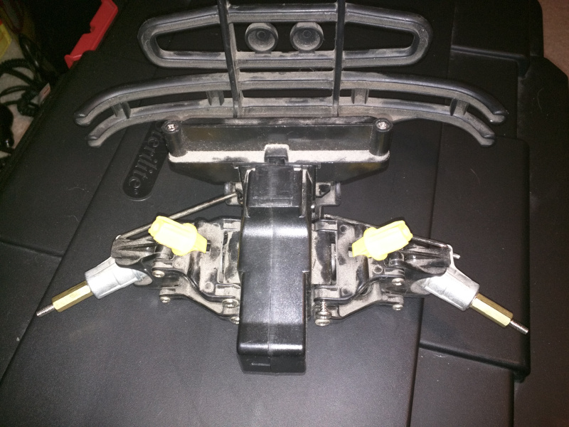
I removed every screw I could find and then split it apart down the middle. The truck had four wheel drive and here you can see the front diff.
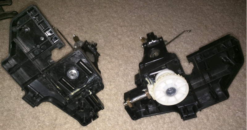
Here is the original servo and the one that will replace it.
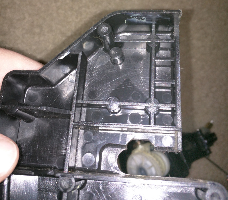
Here is the servo mount. The old servo just sat right in that larger open square.
The futaba servo is just about the right length and width to fit, but the mounting arms need to be removed.
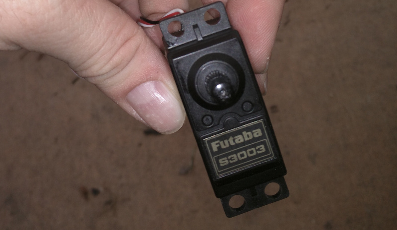
I used a dremel cutoff wheel and cut the mounting arms off.
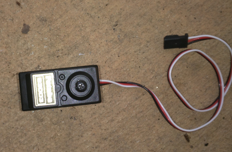
The servo is now the correct length and width, but the case has a small plastic screw post in the way which needs to be cut out.
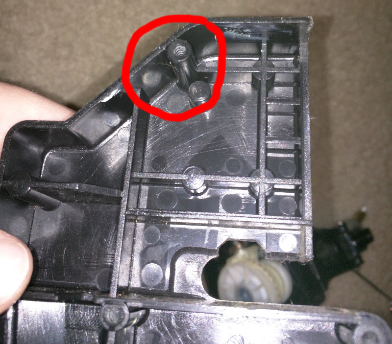
I ground out the screw post and fitted the servo. It was almost there, but the corner of the servo was just barely too large to fit in the space correctly, so I needed to cut out a little window for it to fit.
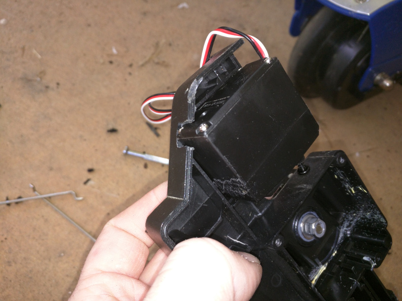
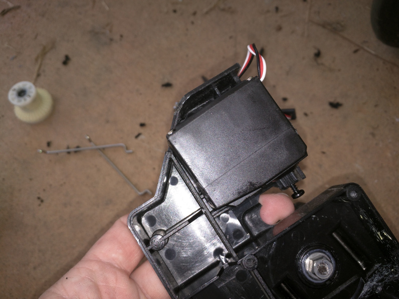
Once that was done, everything looked good. I closed the case back up and the servo was a little loose, so I shoved a lego piece in behind it and it fit like a charm.
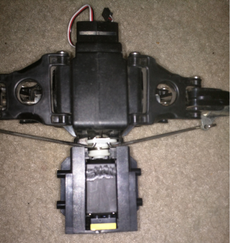
I was then able to put the chassis back together and test out the motors. Now I just need to get the motors moving.