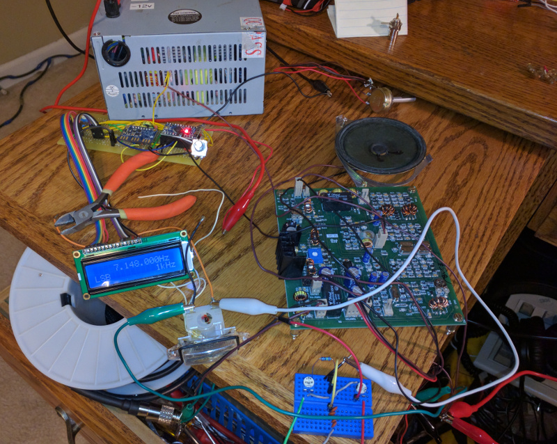
I added an arduino/SI5351 vfo that I had previously made for a dc receiver to my new bitx40 module. I tweaked the arduino code to add the offset, and added a low pass filter to the output of the SI5351. On the bitx board, I desoldered a leg of the L4 coil and plugged the output of the SI5351 to the DDS pins and it worked perfectly.
Here is the code that I used for the vfo. It still needs some cleanup and I plan to add a few more features, but it is enough to get the vfo working. It is based on code from Jason Mildrum, NT7S, Przemek Sadowski, SQ9NJE, and Tom Hall, AK2B.
  1
  2
  3
  4
  5
  6
  7
  8
  9
 10
 11
 12
 13
 14
 15
 16
 17
 18
 19
 20
 21
 22
 23
 24
 25
 26
 27
 28
 29
 30
 31
 32
 33
 34
 35
 36
 37
 38
 39
 40
 41
 42
 43
 44
 45
 46
 47
 48
 49
 50
 51
 52
 53
 54
 55
 56
 57
 58
 59
 60
 61
 62
 63
 64
 65
 66
 67
 68
 69
 70
 71
 72
 73
 74
 75
 76
 77
 78
 79
 80
 81
 82
 83
 84
 85
 86
 87
 88
 89
 90
 91
 92
 93
 94
 95
 96
 97
 98
 99
100
101
102
103
104
105
106
107
108
109
110
111
112
113
114
115
116
117
118
119
120
121
122
123
124
125
126
127
128
129
130
131
132
133
134
135
136
137
138
139
140
141
142
143
144
145
146
147
148
149
150
151
152
153
154
155
156
157
158
159
160
161
162
163
164
165
166
167
168
169
170
171
172
173
174
175
176
177
178
179
180
181
182
183
184
185
186
187
188
189
190
191
192
193
194
195
196
197
198
199
200
201
202
203
204
205
206
207
208
209
210
211
212
213
214
215
216
217
218
219
220
221
222
223
224
225
226
227
228
229
230
231
232
233
234
235
236
237
238
239
240
241
242
243
244
245
246
247
248
249
250
251
252
253
254
255
256
257
258
259
260
261
262
263
264
265
266
267
|
#include <Rotary.h>
#include <si5351.h>
#include <Wire.h>
#include <LiquidCrystal.h>


#define F_MIN        100000000UL               // Lower frequency limit
#define F_MAX        5000000000UL

#define ENCODER_A    2                      // Encoder pin A
#define ENCODER_B    3                      // Encoder pin B
#define ENCODER_BTN  11
#define LCD_RS		5
#define LCD_E		  6
#define LCD_D4		7
#define LCD_D5		8
#define LCD_D6		9
#define LCD_D7		10

LiquidCrystal lcd(LCD_RS, LCD_E, LCD_D4, LCD_D5, LCD_D6, LCD_D7);       // LCD - pin assignement in
Si5351 si5351;
Rotary r = Rotary(ENCODER_A, ENCODER_B);
volatile int32_t LSB = -1199950000ULL;
volatile int32_t USB = -1200150000ULL;
volatile int32_t bfo = -1200150000ULL; //start in usb
//These USB/LSB frequencies are added to or subtracted from the vfo frequency in the "Loop()"
//In this example my start frequency will be 14.20000 plus 9.001500 or clk0 = 23.2015Mhz
volatile int32_t vfo = 700000000ULL / SI5351_FREQ_MULT; //start freq - change to suit
volatile uint32_t radix = 100;	//start step size - change to suit
boolean changed_f = 0;
String tbfo = "";

//------------------------------- Set Optional Features here --------------------------------------
//Remove comment (//) from the option you want to use. Pick only one
#define IF_Offset //Output is the display plus or minus the bfo frequency
//#define Direct_conversion //What you see on display is what you get
//#define FreqX4  //output is four times the display frequency
//--------------------------------------------------------------------------------------------------


/**************************************/
/* Interrupt service routine for      */
/* encoder frequency change           */
/**************************************/
ISR(PCINT2_vect) {
  unsigned char result = r.process();
  if (result == DIR_CW)
    set_frequency(1);
  else if (result == DIR_CCW)
    set_frequency(-1);
}
/**************************************/
/* Change the frequency               */
/* dir = 1    Increment               */
/* dir = -1   Decrement               */
/**************************************/
void set_frequency(short dir)
{
  if (dir == 1)
    vfo += radix;
  if (dir == -1)
    vfo -= radix;

   changed_f = 1;
}
/**************************************/
/* Read the button with debouncing    */
/**************************************/
boolean get_button()
{
  if (!digitalRead(ENCODER_BTN))
  {
    delay(20);
    if (!digitalRead(ENCODER_BTN))
    {
      while (!digitalRead(ENCODER_BTN));
      return 1;
    }
  }
  return 0;
}

/**************************************/
/* Displays the frequency             */
/**************************************/
void display_frequency()
{
  uint16_t f, g;

  lcd.setCursor(3, 0);
  f = vfo / 1000000; 	//variable is now vfo instead of 'frequency'
  if (f < 10)
    lcd.print(' ');
  lcd.print(f);
  lcd.print('.');
  f = (vfo % 1000000) / 1000;
  if (f < 100)
    lcd.print('0');
  if (f < 10)
    lcd.print('0');
  lcd.print(f);
  lcd.print('.');
  f = vfo % 1000;
  if (f < 100)
    lcd.print('0');
  if (f < 10)
    lcd.print('0');
  lcd.print(f);
  lcd.print("Hz");
  lcd.setCursor(0, 1);
  lcd.print(tbfo);
  //Serial.println(vfo + bfo);
  //Serial.println(tbfo);

}

/**************************************/
/* Displays the frequency change step */
/**************************************/
void display_radix()
{
  lcd.setCursor(9, 1);
  switch (radix)
  {
    case 1:
      lcd.print("    1");
      break;
    case 10:
      lcd.print("   10");
      break;
    case 100:
      lcd.print("  100");
      break;
    case 1000:
      lcd.print("   1k");
      break;
    case 10000:
      lcd.print("  10k");
      break;
    case 100000:
      //lcd.setCursor(10, 1);
      lcd.print(" 100k");
      break;
      //case 1000000:
      //lcd.setCursor(9, 1);
      //lcd.print("1000k"); //1MHz increments
      //break;
  }
  lcd.print("Hz");
}


void setup()
{
  Serial.begin(19200);
  lcd.begin(16, 2);                                                    // Initialize and clear the LCD
  lcd.clear();
  Wire.begin();

  si5351.set_correction(140); //**mine. There is a calibration sketch in File/Examples/si5351Arduino-Jason
  //where you can determine the correction by using the serial monitor.

  //initialize the Si5351
  si5351.init(SI5351_CRYSTAL_LOAD_8PF, 0); //If you're using a 27Mhz crystal, put in 27000000 instead of 0
  // 0 is the default crystal frequency of 25Mhz.

  si5351.set_pll(SI5351_PLL_FIXED, SI5351_PLLA);
  // Set CLK0 to output the starting "vfo" frequency as set above by vfo = ?

#ifdef IF_Offset
  //Serial.println((long)((vfo * SI5351_FREQ_MULT) + bfo) * -1);
  si5351.set_freq(((vfo * SI5351_FREQ_MULT) + bfo) * -1, SI5351_PLL_FIXED, SI5351_CLK0);
  volatile uint32_t vfoT = abs((vfo * SI5351_FREQ_MULT) + bfo);
  tbfo = "USB";
  // Set CLK2 to output bfo frequency
  si5351.set_freq( bfo, 0, SI5351_CLK2);
  //si5351.drive_strength(SI5351_CLK0,SI5351_DRIVE_2MA); //you can set this to 2MA, 4MA, 6MA or 8MA
  //si5351.drive_strength(SI5351_CLK1,SI5351_DRIVE_2MA); //be careful though - measure into 50ohms
  //si5351.drive_strength(SI5351_CLK2,SI5351_DRIVE_2MA); //
#endif

#ifdef Direct_conversion
  si5351.set_freq((vfo * SI5351_FREQ_MULT), SI5351_PLL_FIXED, SI5351_CLK0);
#endif

#ifdef FreqX4
  si5351.set_freq((vfo * SI5351_FREQ_MULT) * 4, SI5351_PLL_FIXED, SI5351_CLK0);
#endif

  pinMode(ENCODER_BTN, INPUT_PULLUP);
  PCICR |= (1 << PCIE2);           // Enable pin change interrupt for the encoder
  PCMSK2 |= (1 << PCINT18) | (1 << PCINT19);
  sei();
  display_frequency();  // Update the display
  display_radix();
}


void loop()
{
  // Update the display if the frequency has been changed
  if (changed_f)
  {
    display_frequency();

#ifdef IF_Offset
    //Serial.println((long)((vfo * SI5351_FREQ_MULT) + bfo) * -1);
    si5351.set_freq(((vfo * SI5351_FREQ_MULT) + bfo) * -1, SI5351_PLL_FIXED, SI5351_CLK0);
    //you can also subtract the bfo to suit your needs
    //si5351.set_freq((vfo * SI5351_FREQ_MULT) - bfo  , SI5351_PLL_FIXED, SI5351_CLK0);

    if (vfo >= 10000000ULL & tbfo != "USB")
    {
      bfo = USB;
      tbfo = "USB";
      si5351.set_freq( bfo, 0, SI5351_CLK2);
      Serial.println("We've switched from LSB to USB");
    }
    else if (vfo < 10000000ULL & tbfo != "LSB")
    {
      bfo = LSB;
      tbfo = "LSB";
      si5351.set_freq( bfo, 0, SI5351_CLK2);
      Serial.println("We've switched from USB to LSB");
    }
#endif

#ifdef Direct_conversion
    si5351.set_freq((vfo * SI5351_FREQ_MULT), SI5351_PLL_FIXED, SI5351_CLK0);
    tbfo = "";
#endif

#ifdef FreqX4
    si5351.set_freq((vfo * SI5351_FREQ_MULT) * 4, SI5351_PLL_FIXED, SI5351_CLK0);
    tbfo = "";
#endif

    changed_f = 0;
  }

  // Button press changes the frequency change step for 1 Hz steps
  if (get_button())
  {
    switch (radix)
    {
      case 1:
        radix = 10;
        break;
      case 10:
        radix = 100;
        break;
      case 100:
        radix = 1000;
        break;
      case 1000:
        radix = 10000;
        break;
      case 10000:
        radix = 100000;
        break;
      case 100000:
        radix = 1;
        break;
    }
    display_radix();
  }
}
|

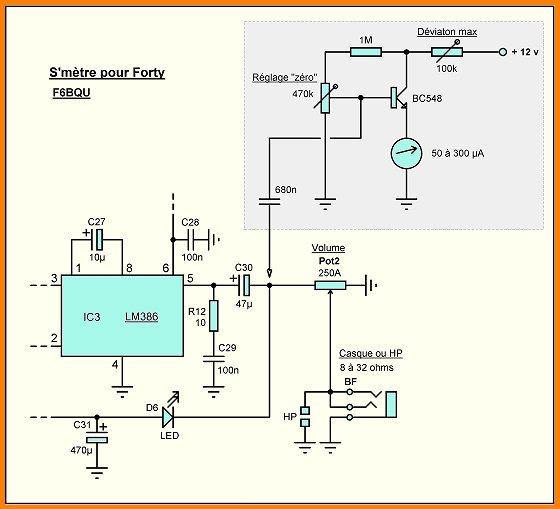
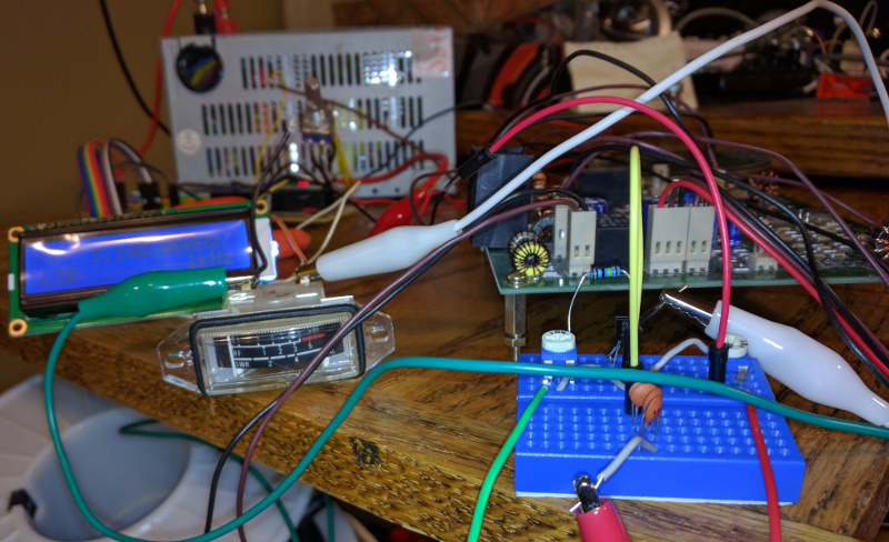
I found this circuit for an s meter and put it together on a small breadboard and used an old s/swr meter. It works okay, but it needs some work. I will probably add an swr bridge and use the same meter for both.


I still need to put it all together in a box. I looked at buying a bending brake and some sheet metal, but it was just too pricey for me at the moment. I did find an old rack mount firewall that has a built in 12v power supply that I may try to use if I can fit everything inside.


