homebrew z80 computer
A while back I found the RC2014 project which is a modular z80 computer. I’ve been wanting to play around with the z80 and this looked like a good place to start considering I already had most of the parts.
The RC2014 is designed around modules that plug into a back plane. There are many modules available, most of which have published schematics, so it was fairly easy to get started.
I started with the power supply. I just put together a simple 7805 regulator circuit and soldered it on a piece of strip board.

Next, I added a row of header sockets and built a simple adjustable 555 clock circuit. This would let me speed up/slow down the clock during testing.

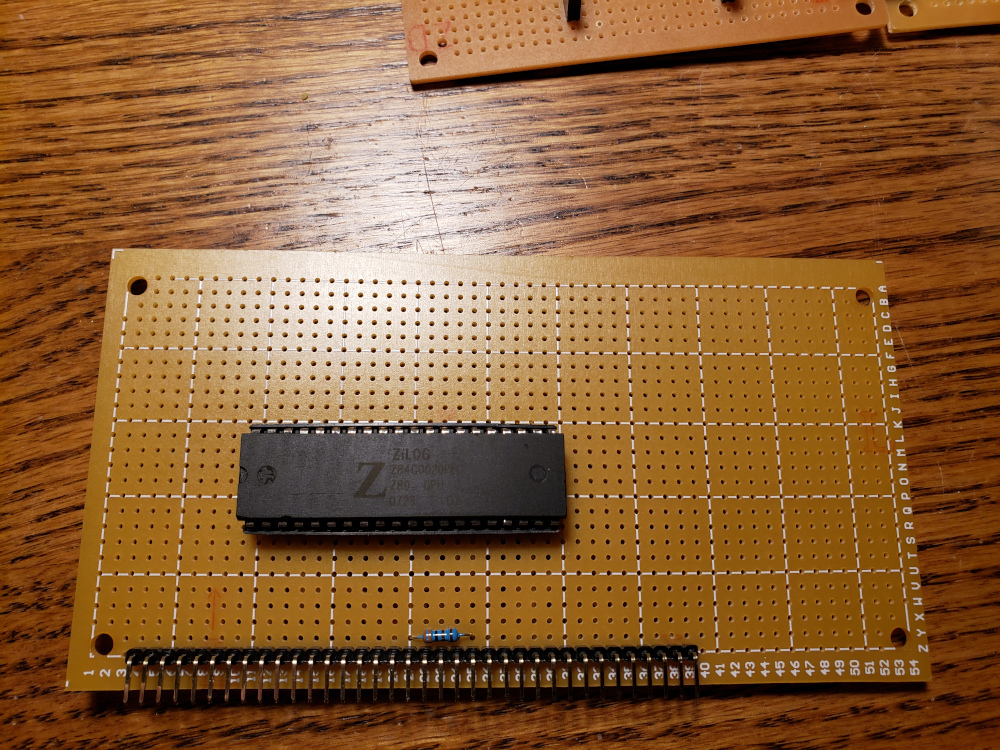
Next was the CPU which is the simplest module of the bunch. It only requires a z80 cpu and a resistor.

Next is the switchable ROM board. I didn’t have the 27c512 that the RC2014 used, but I did have some 28c256 rom chips. I modified the circuit a bit and used that instead. Since it is 32k instead of the 64k, I only have two jumpers to select between four 8k banks.


I extended the back plane a bit. I added a set of right angle sockets and headers to connect two strip boards together.


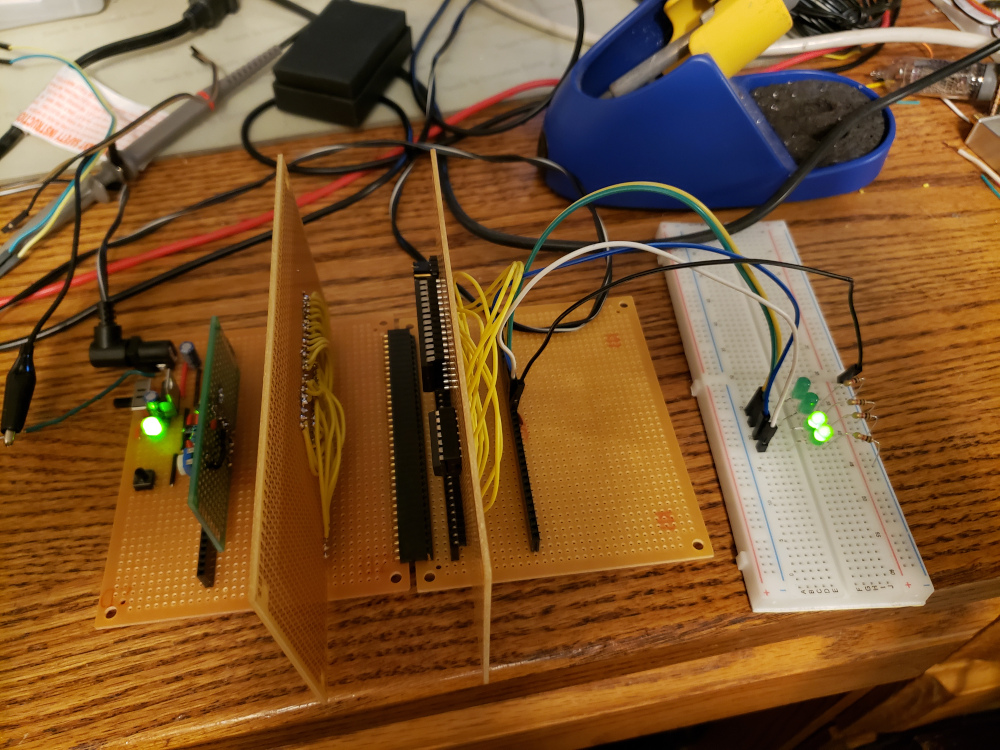
That was enough to get things tested. In the image below, I’ve plugged in the slow clock, CPU, and a ROM into the backplane.
I’ve got the first few address lines wired over to a breadboard with some LEDs. The z80 starts reading the ROM at 0x000 which is programmed with 0x00 NOP instructions.
This causes the z80 to incrementally read the address lines which lights up the LEDs as a binary counter.
Everything was looking good with the test, so I started building up the other modules.
I made a quick fast clock circuit on a piece of scrap. Eventually, i will probably combine the clock with another module that has some free space on the board, but for now, this will work.


Below is a 64k ram board.


During testing, I was having trouble with the 64k RAM board, so I built a simpler 32k board that you see below.


I had a z80 SIO chip available, so I went with that over the RC2014’s standard serial module. The SIO chip has two available serial ports.


I got everything built and plugged into the back plane and I was getting some response over the serial port, but everything was very inconsistent.
In the image below, you can see where I could initially get the “Cold or warm start” prompt” and then it would freeze.
On reset, sometimes it would get a little further and then output some errors or gibberish characters.

At this point, I wasn’t quite sure what was going on. I thought it may have been a problem with the serial board, so I built up a different board using a MC6850P.


The new serial board didn’t work at all.
The clue that finally made me look at the datasheets was when I noticed in the serial board above, I used a MC6850 not a MC68B50 like the RC2014. The datasheet states that the MC6850 is only good up to 1MHz.
I checked my z80 I was using and it was only good up to 4MHz. I was running the clock at 7MHz.

I ordered a 20MHz z80 chip and swapped it out and voila! Everything worked as expected (Using the z80 SIO serial board).
The images below show the full computer working for the first time.
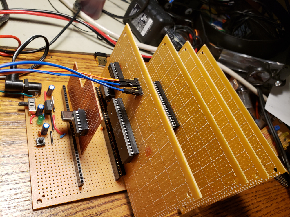
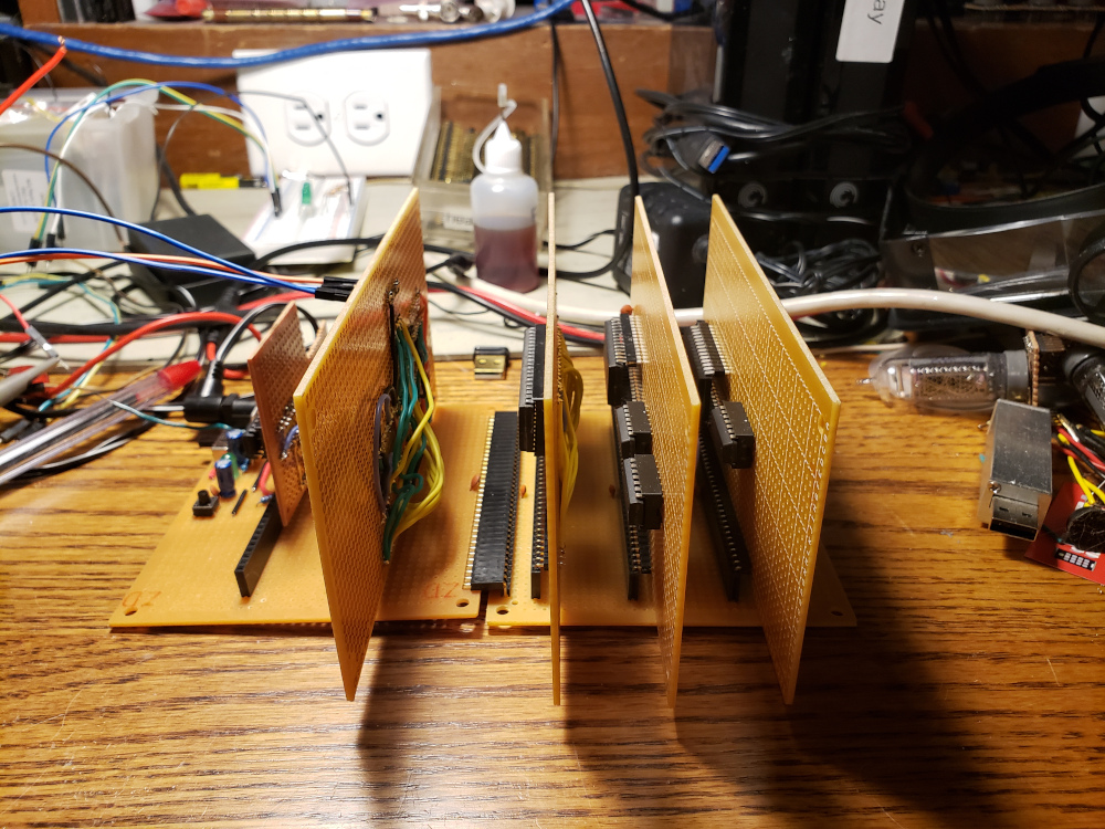

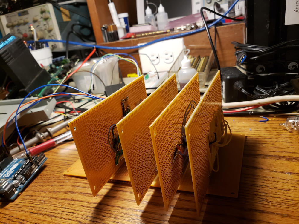
I connected to it using an FTDI connection and wrote a quick basic program, and it worked!

Now I need to get that 64k RAM board working and build some more modules for this thing! I’d like to add a “disk” and get CP/M running.