MiniPA 70 Mosfet Amplifier
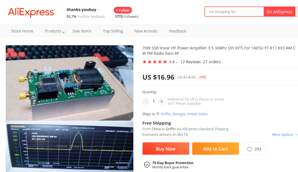
A while back, I picked up a cheap amplifier kit off aliexpress for a few bucks and finally got around to finishing it.
It will supposedly put out 70 watts using a pair of IRF530N mosfets.
The build itself was pretty straight forward. The surface mount components were already soldered on the board.
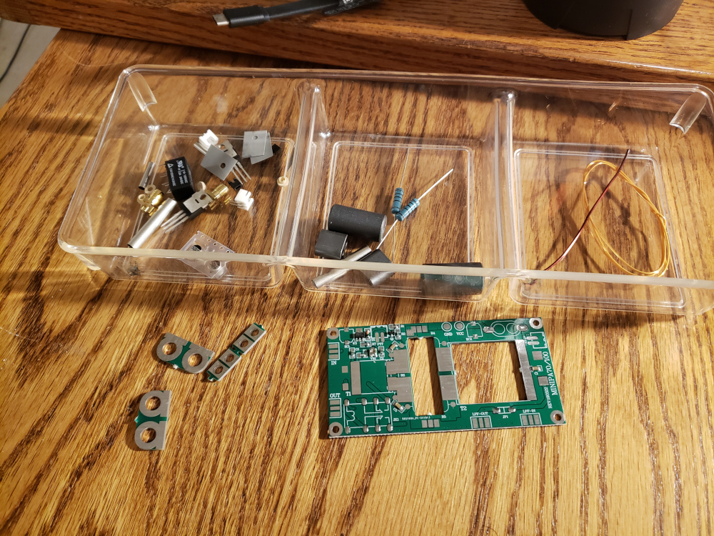
They have these weird metal tubes that you have to assemble and solder to PC board material that make up one of the turns to the transformer. That was probably the hardest part of the build.

The kit didn’t come with a heat sink. I found one in the junk box that was about the right size. I think it came off of a pentium 3. It had a fan attached which was cool.
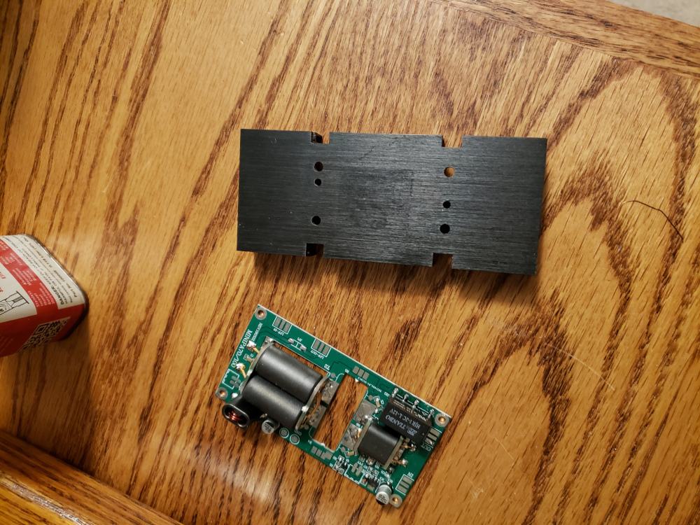
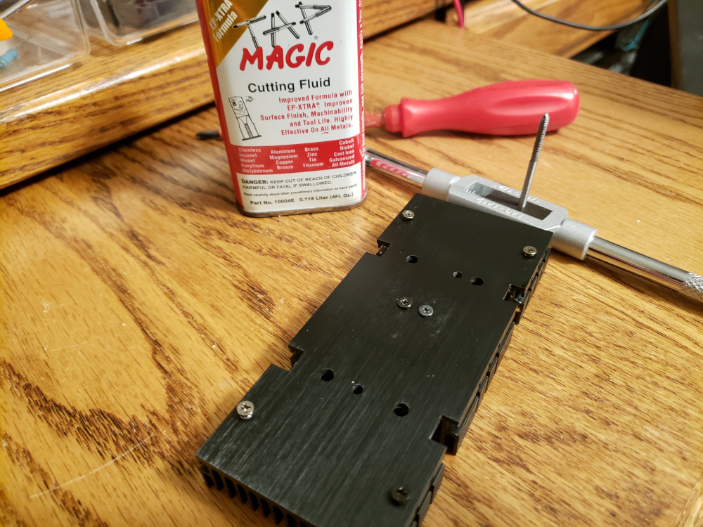
I drilled and tapped mounting holes for the board and the mosfets.
I mounted the board and soldered the rest up and tested it.
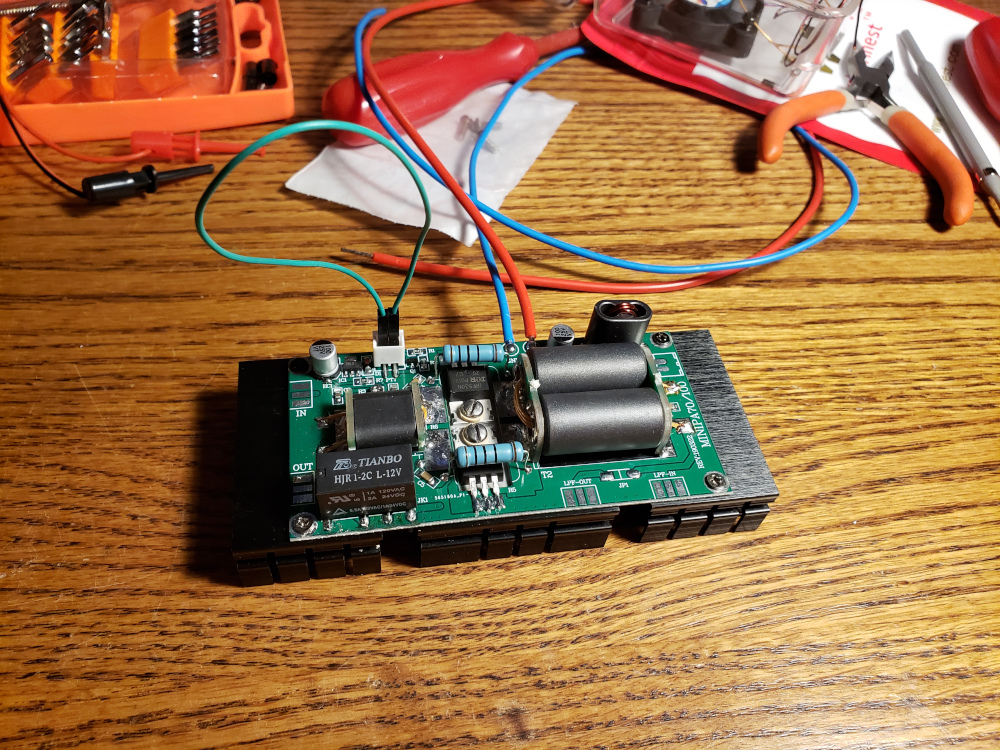
It worked, but not very well. The input SWR was like 5:1, so I tried a few different resistor combinations across the secondary of the input transformer. I ended up with two 33 ohm 1 watt resistors in parallel. That gave me the best input SWR.

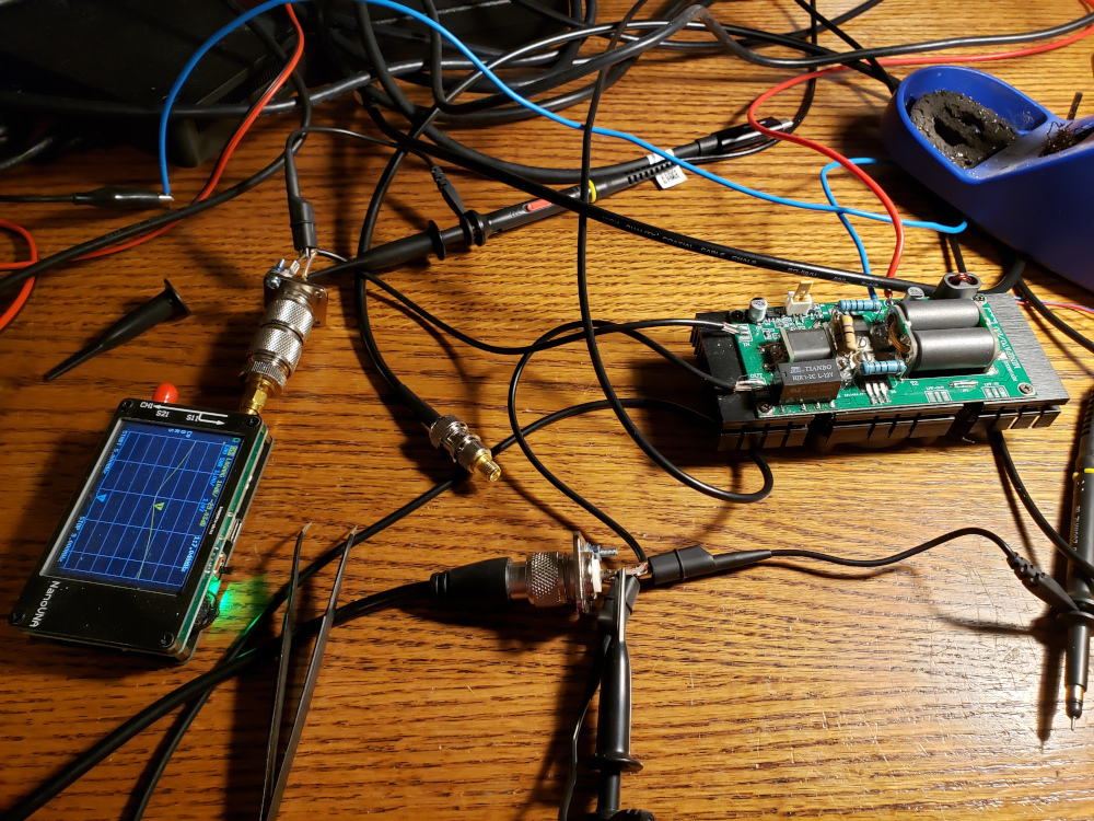
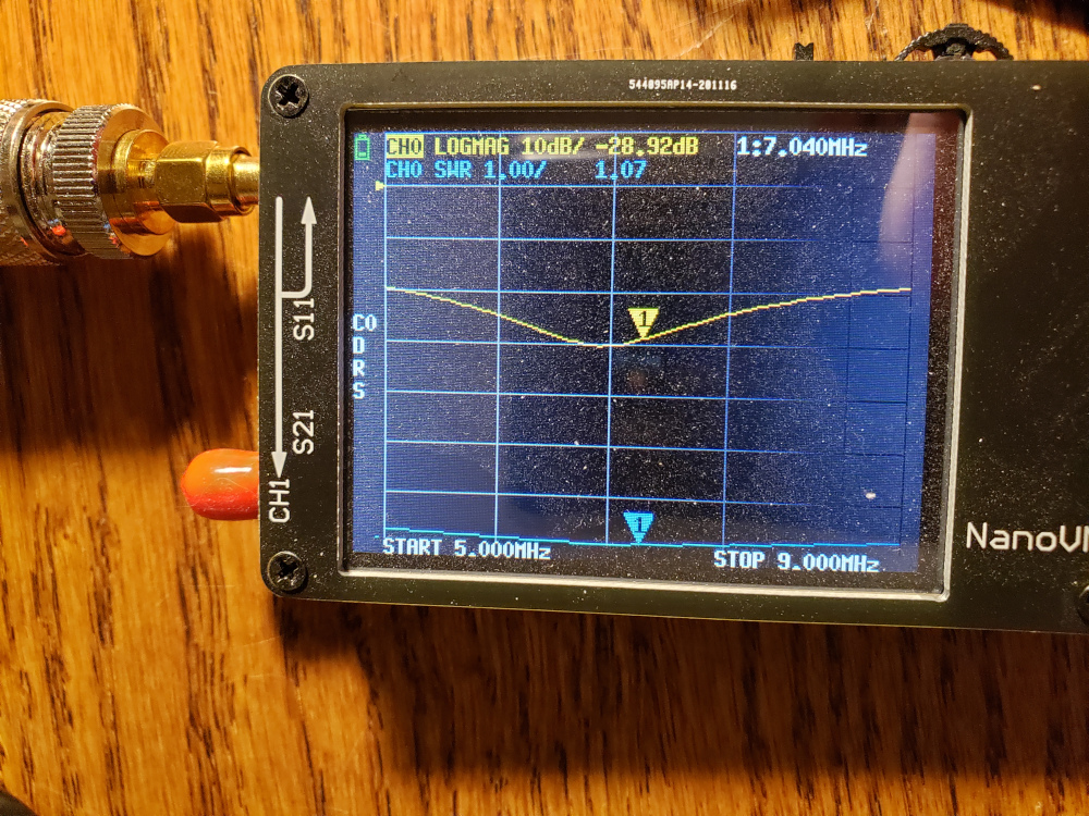
I tweaked the bias until I got the best output signal. It ended up being around 3.5 volts. I had to change R7 to a 220 ohm resistor to give me a better range on the bias potentiometer.
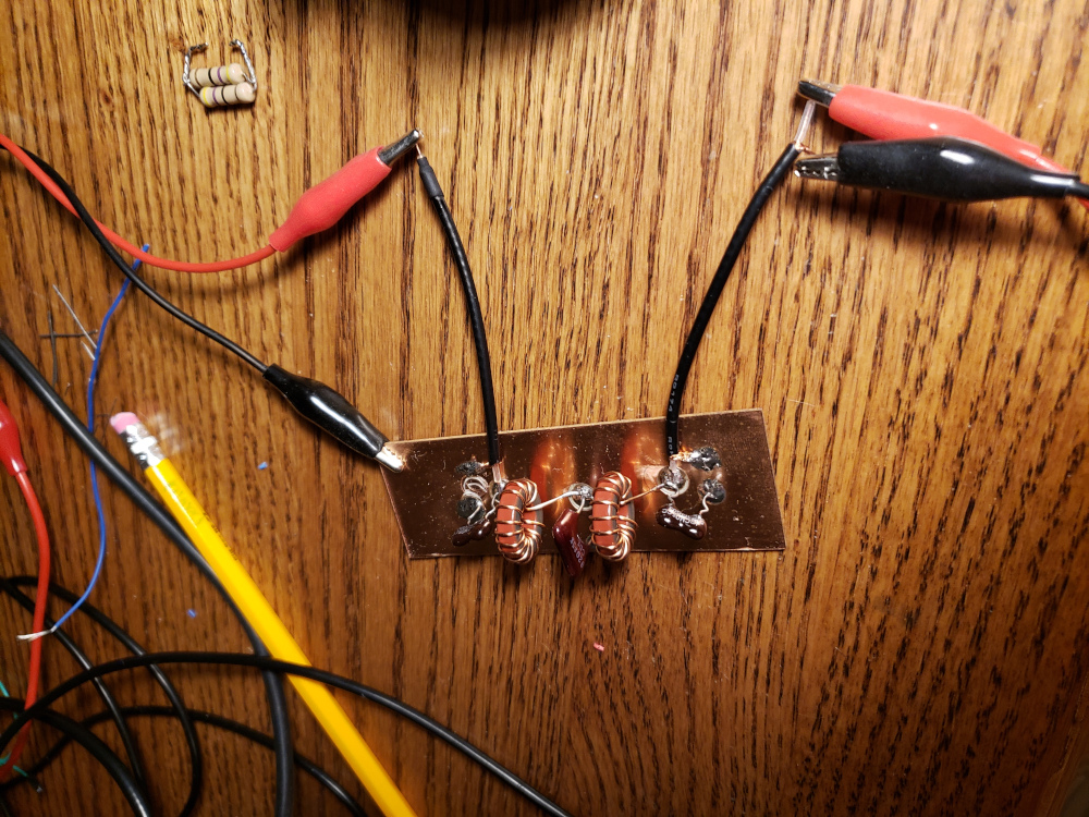
The output waveform was still a little distorted, so I added a low pass filter for 40 meters using the calculator below.
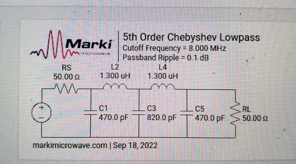
I didn’t have the exact components on hand. I used the closest values I had and it worked out okay.
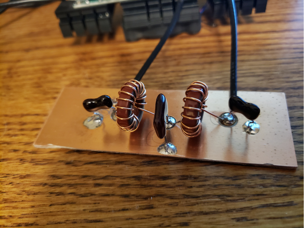
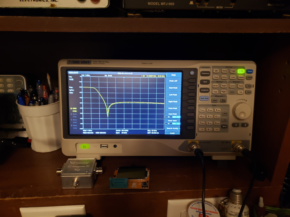
I hooked it up to the spectrum analyzer. It seems good to me, but I’m still learning how to use this thing.
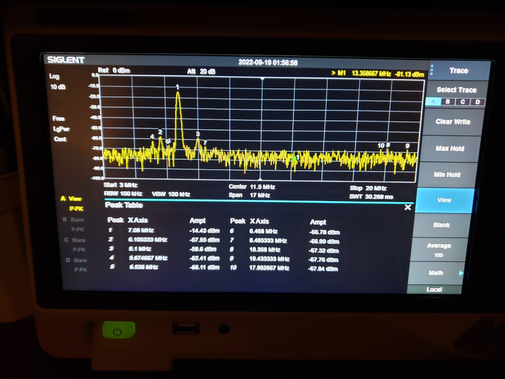
Once everything seemed good, I put it on the air. I wasn’t getting anywhere near 70 watts. According to my meters, the best I could get was about 35 watts into my EFHW antenna, but paired with the QDX and FT8, I was getting some good range. My first QSO with the amplifier was to the Canary Islands which is about 4000 miles from me.
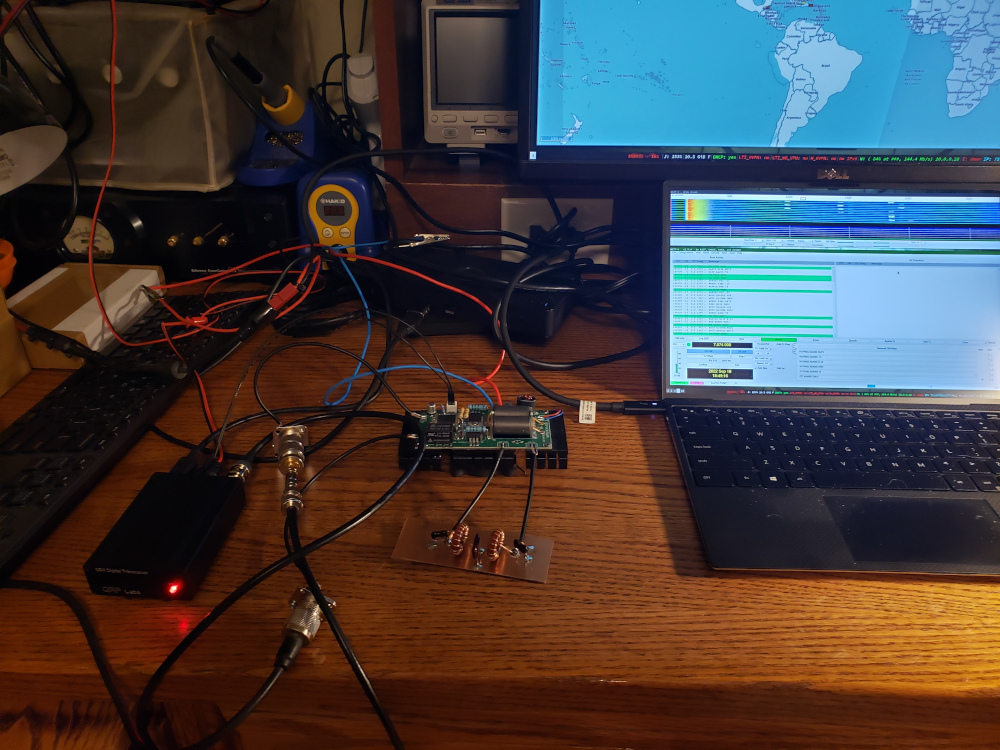
The amplifier worked well for about two days and then the mosfets went up in smoke. I’m not sure what happened, but I’ve ordered replacements.
There are numerous mods floating about on the net for these amps. I may try a few to avoid smoking more mosfets. Some good information can be found here: https://f5npv.wordpress.com/irf530-mosfet-amplifier/
You can also find some good youtube videos of people building and testing these amps. NA5Y has a few videos on his channel.
**** EDIT - Updated 2022-10-03 *****
After blowing a few sets of IRF530Ns and repairing a few traces that were blown away by the spectacular failures, I added a string of six 1n4148 diodes in series from the output of R7 to ground. I thermally coupled the diodes to the MOSFETs and that seems to have helped prevent some of the thermal runaway conditions that happen with these amps.
Since I’ve added the diodes, I’ve been running the amp pretty heavily on FT8 at about 15 volts and have been getting about 50 watts output and making some pretty impressive contacts.