oscillators
I’ve been reading some older qrp circuit design books and wanted to play around with some of the oscillators. With the audio amp from a recent post, I may have the start of a little qrp receiver or possibly a transceiver.
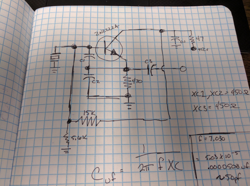
I started with a simple colpitts oscillator. The schematic below is what I used. For the capacitors, you can see the capacitive reactance to the right. Using the formula at the bottom, you can calculate the capacitor values for the desired frequency. I used a 7.030 crystal, so the capacitors came out to 50pf.
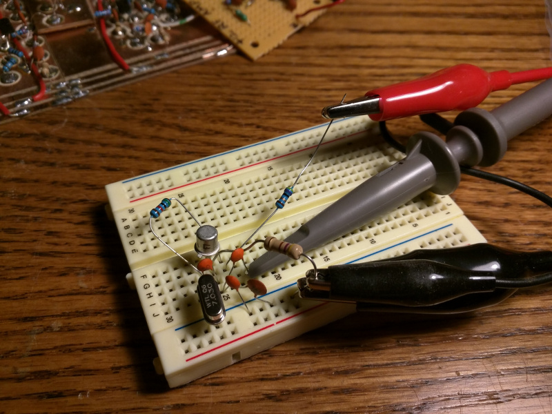
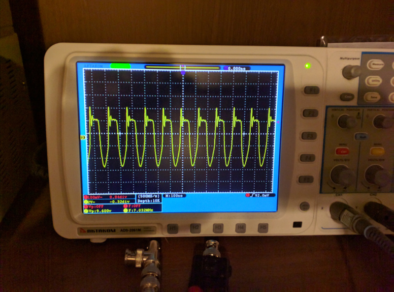
I built the circuit on a breadboard and had a pretty ugly waveform from it, but this was more or less for experimentation rather than any practical use.
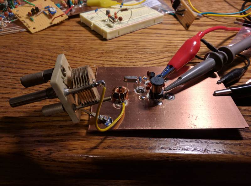
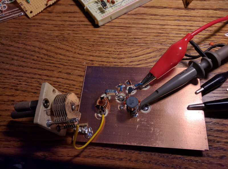
Next, I went for a vxo that followed the colpitts design. The same formula from before can be used for this schematic. For the inductors, you can use the formula, [ inductance in uH = XL / 2 * π * (frequency in MHz) ]
I used a 7.030MHz crystal again, so my capacitors came out to 50pf, and the inductor RFC1 = 283uH, and XL1 = 22.7uH.
The closest I came with RFC1 was a 150uH coil, so I went with that and it worked okay. I don’t think the values for the components are super critical so some experimentation is probably a good thing.
I used a J310 for the jfet at the center of the oscillator and the rest of the components I used as listed in the schematic.
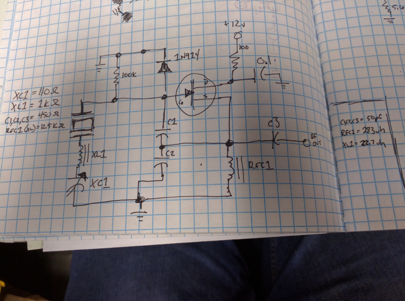
I just grabbed a random air variable cap. I didn’t even measure it, but the circuit works pretty well.
My scope has a pretty bad frequency counter in it, but it showed that this vxo could pull the crystal frequency about 10kHz. I’ll try to hook up a better frequency counter and see if I can get a more accurate measurement this weekend.
